
Your first five minutes
Open an example, look around, watch how it was built, set a Jig and export a part for a 3D printer. No AI agent needed.
You need 3DCraft installed, or the web version open in your browser (Install 3DCraft).
1. Open an example
Start 3DCraft. Without a document, the window shows its start screen:
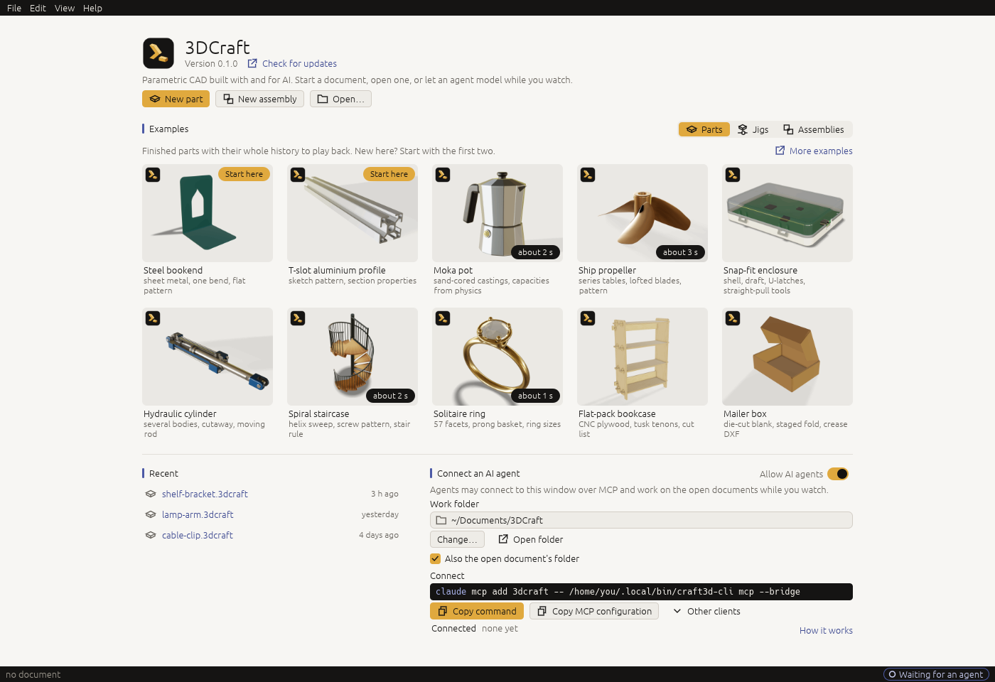
At the top are New part, New assembly and Open…. Under them, Examples has three tabs at its right: Parts, Jigs and Assemblies. Only the cards of the chosen tab show; it starts on Parts.
Under Parts, the first two cards, marked Start here, are simple: a steel bookend and a T-slot aluminium profile. Click the T-slot aluminium profile card. 3DCraft opens it in a new tab.
It is a 30 × 30 mm aluminium profile, the kind machine frames and 3D-printer frames are built from: four T-slots along its length, sawn to 300 mm, with a threaded hole in each end.
The profile has two sizes you may change, so it opens on its Parameters tab. Click the Features tab next to it.
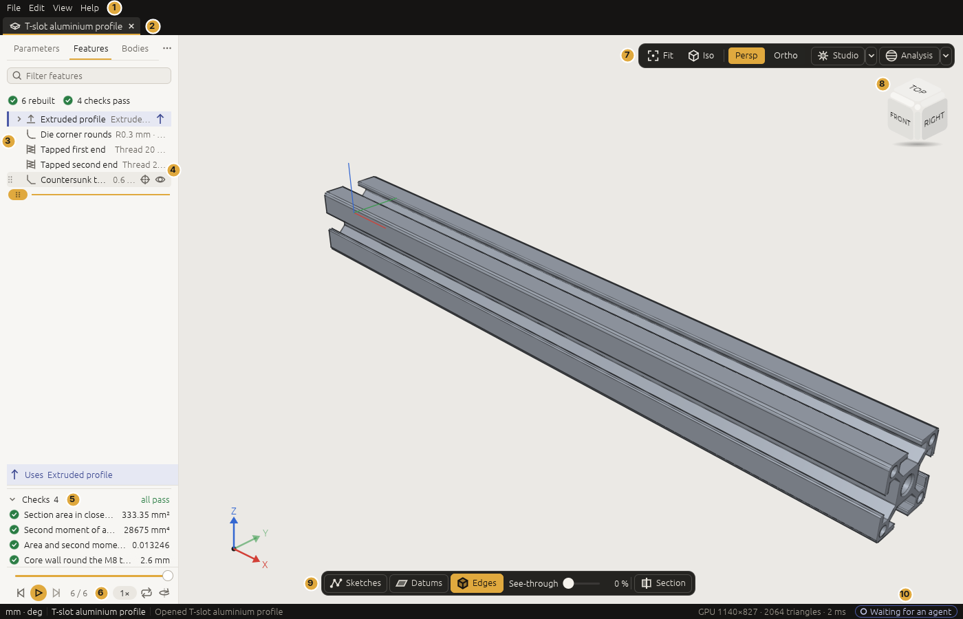
In this picture the pointer rests on the last row, which shows that row's grip, its ⌖ and its eye (The window › Features explains them). Like most pictures in this guide, it was taken with Sketches and Datums switched off, the first two buttons at the foot of the view. In your window Sketches is on until you switch it off, so you also see the lines of the sketches; Datums starts off: switch it on to see the datum planes and axes.
On the left is the feature list: the steps that made the profile, in order.
| Step | What it made |
|---|---|
| Cross section | A sketch of the profile's outline: one quarter drawn, then turned round three more times. It is folded under the next row; click › to see it |
| Extruded profile | The outline pushed out to the profile's length |
| Die corner rounds | The 32 small inside corners of the slots, rounded as the extrusion die leaves them |
| Tapped first end, Tapped second end | An M8 thread in the hole at each end |
| Countersunk thread entries | A small cone at the mouth of each thread |
Under the list are the checks (the commands call them assertions). These are what the profile must pass, measured on the model: its cross-section's area and stiffness against formulas worked out by hand, a comparison with a maker's catalogue, and the wall round the thread. A ✔ means it passes.
2. Look around
| Do this | To |
|---|---|
| Drag with the left mouse button | Turn the model (orbit) |
| Drag with the right button (or Shift and the left) | Move it (pan) |
| Turn the wheel, or pinch on a touchpad | Zoom in and out, about the point under the pointer |
| Click a side or corner of the view cube (top right) | Look from the front, the top, a corner, … |
| Press F, or click Fit | See the whole model again |
Now click the Die corner rounds row: the rounded corners light up in the view. Double-click the row (or click the ⌖ that appears on it) and the camera flies to them. Press F to see everything again.
Tip: the eye at the end of a row hides that step's body or sketch in the view. Click it again to show it. The model itself does not change.
3. Watch how it was built
Under the feature list is the history player, like a video player:

- Point at the view and press Home, or drag the timeline to its left end. The view shows the model after the first step: only the sketch of the cross section.
- Press Space, or click the round play button. The profile is built again, step by step, with the
name of each step at the top of the view. The player counts the steps:
1 / 6,2 / 6, … - Click Orbit, the last button of the row, and play again: the camera turns slowly while it plays. The player's buttons are icons: hold the pointer on one to see its name.
- Press End to see the finished part again.
Playing back never changes the document; it only shows it as it was.
4. Change a size
Click the Parameters tab. Click the value of Length, type 500 mm and press Enter. The profile
grows to 500 mm, and its checks are measured again: they still pass, because a longer profile has the
same cross section.
Click ↺ beside Length to put it back.
5. Set a Jig
A Jig is a finished design with a form: the sizes that matter are fields, and the rest follows. Close the profile's tab (File › Close, or Ctrl+W; if 3DCraft asks whether to save, choose Don't Save). The start screen comes back.
Click Jigs above the cards, then the Gridfinity bin card: a storage bin for the Gridfinity system, printed without supports. It opens on its Parameters tab.
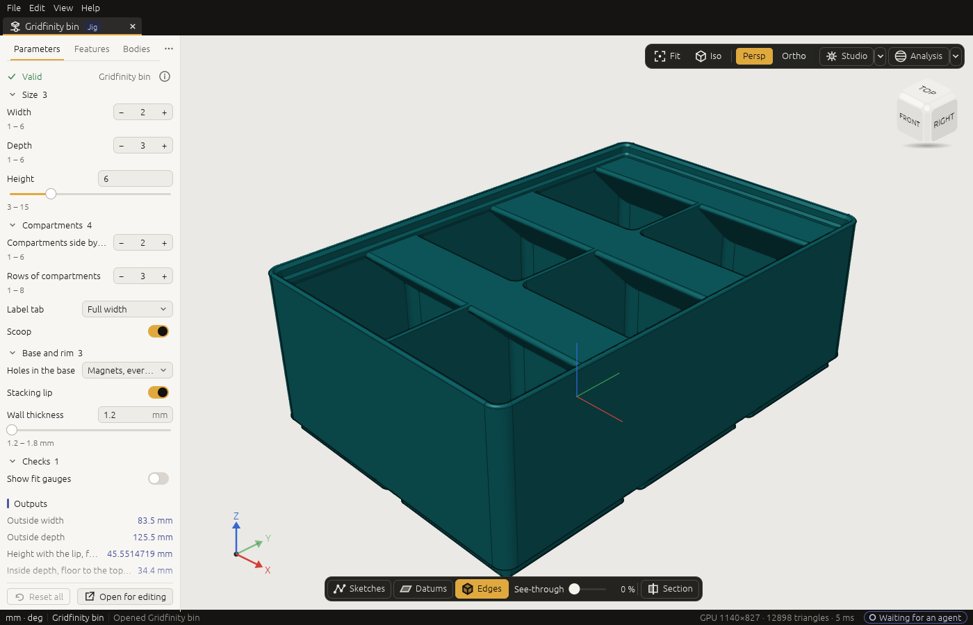
- Drag the knob of the Height slider. The bin's walls grow and shrink in steps of 7 mm, the height unit of the Gridfinity system, as you drag.
- Beside Width, click +: the width goes from 2 to 3 grid units of 42 mm, and the compartments get wider.
- Beside Compartments side by side, click +: nine compartments now, three across and three deep. At the panel's first width this name is cut short, Compartments side by…: hold the pointer on it to read it whole, or drag the panel's right edge to widen it.
- Turn off the Scoop switch: the rounded fronts inside the compartments go.
- Click ↺ beside a parameter to put it back, or Reset all to put them all back.
Leave Show fit gauges off: the gauges are extra bodies that prove the bin fits a baseplate, and an export would write them too.
6. Export it for a 3D printer
-
Open the File menu and choose Export… (or press Ctrl+E; ⌘E on a Mac).
-
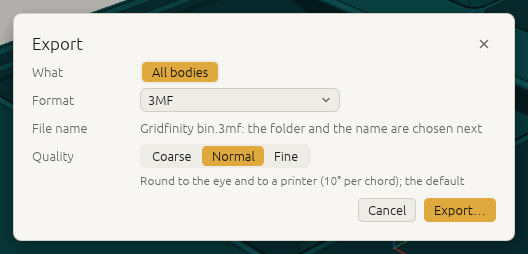
In the export dialog, keep All bodies and choose the format 3MF. 3MF keeps the size unit and the colours; most slicers read it, and STL as well. The quality: Normal is right for printing.
-
Click Export…, choose where in your system's save dialog, and click Save.
Open the file in your slicer (PrusaSlicer, Cura, Bambu Studio, OrcaSlicer, …). The bin stands on its feet, in millimetres, as designed. It prints without supports.
A laser cutter instead? The Laser-cut box under Jigs works the same way. Its export is a cut sheet: in the export dialog choose Sheet of set: Cut sheet and SVG or DXF, and every panel comes out on one flat sheet at true size, ready for your laser software (Files › Laser cutting).
For another CAD program, export STEP (Files › Other CAD programs). Files, export and drawings describes every format.
7. Save
File › Save (Ctrl+S) saves the document as a .3dcraft file. A Jig is never overwritten: saving it
saves your settings as a new .3dcraft model. If you forget to save, 3DCraft keeps an autosave and
offers to recover it after a crash (Troubleshooting).
What next?
- Design something new with an AI agent: connect one (Install › Connect an AI agent) and read Working with an AI agent.
- Get to know the window: The window.
- More Jigs: Using a Jig describes the six on the start screen.
- More examples: More examples on the start screen opens the examples gallery, 3dcraft.dev/examples, in your browser. The guide's own lessons are seven short command scripts (the lessons) that you run yourself, as A first part, command by command shows.
Next: Working with an AI agent.