
Files, export and drawings
Save your design, bring in parts from other CAD programs, and export for 3D printing, laser cutting, other CAD programs and drawings.
| Format | Open or import | Save or export | Holds |
|---|---|---|---|
.3dcraft |
Open… (file.open) |
Save (file.save) |
Your design: its history, variables, sketches, features, checks, sets, colours |
.3dcraftjig |
Open… (file.open) |
Export as Jig… (jig.export) |
A design to be set by its parameters, with its info and a picture (Using a Jig) |
STEP (.step, .stp) |
Import… (file.import) |
Export… (file.export) |
Exact solids, units, names, colours; no history. For other CAD programs |
FreeCAD (.FCStd), BRep (.brep) |
Import… (file.import) |
no | The finished objects as exact solids, with their names, places and colours; no history |
| STL, 3MF, OBJ | no | Export… | Triangle meshes, for 3D printing and rendering |
| DXF, SVG | no | Export… | Flat outlines at true size, for laser cutting; or a drawing of the model as seen |
In the window, the File menu does all of this with your system's file dialogs. An agent uses the
commands in brackets. Its paths are relative to its work folder, and it reaches only the folders the agent
panel names (Install › Which files the agent can reach).
craft3d-cli run on its own reads and writes anywhere you can
(The command line and scripts).
Saving: the .3dcraft file
A .3dcraft file holds the recipe, not only the shape: opening it rebuilds the bodies, bit for bit the
same as when it was saved. Saving is safe: a full disk or a crash leaves the previous file as it was.
The promise: every .3dcraft file written by a released version of 3DCraft opens in every later
version and rebuilds to the same bodies. A file from a newer version is refused by an older one with a
message that names both versions, never guessed at.
A Jig (.3dcraftjig) is the same kind of file, published to be used: opening it shows its Parameters tab,
and saving saves your result as a new .3dcraft, never over the Jig (Using a Jig).
Exporting from the window
- File › Export… (Ctrl+E) opens the export dialog.
- Choose What goes into the file, then the Format: only the formats that can hold what you chose are offered. Set the options the format has (below).
- Click Export…. Your system's save dialog opens with the name already ending in the right
extension, in the folder you exported to last. Choose where, and save: the file is written at once.
If you type a name without the extension, or with another format's, 3DCraft names the file for the
format you chose (
partbecomespart.stl), so the file always holds what its name says.
What you can export:
| What | Formats | What you get |
|---|---|---|
| All bodies | STEP, STL, 3MF, OBJ | Every body that is not hidden (the dialog names the hidden ones it leaves out, and so does the status line after the export) |
| DXF, SVG | A drawing of the model as seen | |
| Selection | STEP, STL, 3MF, OBJ | The selected bodies, hidden or not |
| DXF, SVG | The outlines of the selected flat faces, or of one selected sketch, or the flat pattern of one selected sheet-metal part | |
| Sheet of set: … | DXF, SVG | Every flat face of a named set on one sheet (below) |
| Flat pattern of … | DXF, SVG | A sheet-metal part, unfolded (Sheet metal) |
| Crease pattern of … | DXF, SVG | A fold's creases on its paper (Origami) |
| Flat patterns of every part | DXF, SVG | Every sheet-metal part unfolded on one sheet |
Selection is chosen first when something is selected (and the sheet or pattern you exported last from this document, when it still has it). When no format can hold what is selected (an edge, say), the dialog says why and offers all bodies instead.
Bodies you hid with the eye are left out of All bodies, in every format: the dialog names them under All bodies, and the status line names them after the export. To write a hidden body, show it, or select it and export the selection.
3D printing: STL, 3MF and OBJ
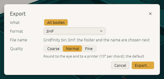
The export dialog asks for the quality: how closely the triangles follow the curved faces.
| Quality | For |
|---|---|
| Coarse | Small files and quick previews; curves in visible steps (20° per triangle side) |
| Normal | Round to the eye and to a printer (10°); the default |
| Fine | Smooth up close: four times finer, 5°, a larger file |
The last quality you chose is offered next time. 3MF is the best choice for printing: it carries the
unit, the bodies' names and their colours. STL is triangles only, in the document's unit (millimetres
unless the design says otherwise). OBJ writes its colours to a material file (.mtl) next to it.
An agent writes the same with:
[
 ["file.export", {"path": "part.3mf"}],
 ["file.export", {"path": "part.stl", "quality": "fine"}],
 ["file.export", {"path": "part.stl", "tolerance": 0.01}]
]
tolerance (in the document's unit) and angle (degrees; 0 for none, else 1 to 90) set the accuracy
yourself; a tolerance alone, with no quality or angle, has no angle criterion. The result says
tolerance, angle, quality and how many meshes are closed (watertight). A mesh of more than 20
million triangles, all bodies together, is refused: choose a coarser quality.
Other CAD programs: STEP
Export, then import a STEP file you have (supplier-part.step stands for its name):
[
 ["file.export", {"path": "part.step"}],
 ["file.import", {"path": "supplier-part.step"}]
]
Export writes every body as an exact solid (AP214), with the document's unit, each body under its
feature's name and with its colours. To export some of the bodies, select them in the window, or name them:
"bodies": ["Bracket", "F4"] (also for STL, 3MF and OBJ). A body switched off by its condition (when) or
suppressed is left out of the list, so one list serves every option of a Jig; cut.list and cut.export take
bodies the same way. Without bodies, a body hidden in the view (feature.visible, the eye in the feature
list) is left out of STEP, STL, 3MF and OBJ, as a drawing leaves it out, and of the cut list; the result's
hiddenLeftOut says which. Named in bodies, a hidden body is written all the same. A body named in bodies
and switched off is listed under switchedOffLeftOut, as the measures do.
Import (File › Import…) reads the solids and sheets of AP203, AP214 and AP242 files, assemblies
too (one feature per placed solid, with their colours), and converts the units. The file is kept inside the
document, so it rebuilds without it. An imported body is a feature like any other: cut it, round it,
measure it. Its faces are named by their order in the file (F5:face(0)). What cannot be read is refused,
naming the part of the file at fault.
A FreeCAD document (.FCStd) imports the same way: one body per finished, visible object (a cut, not
the two shapes it was cut from; a PartDesign body, not its pads and pockets), named after its label, where
FreeCAD placed it and in its colour. Hidden objects are left out and listed in the result. FreeCAD's history
does not come along: the bodies are exact solids, edited here like any other.
Laser cutting: flat outlines in DXF and SVG
Select one or more flat faces, or one sketch, and export to .dxf or .svg: you get the outline
at true size, with its holes. Lines, arcs, circles and splines stay what they are, so the laser follows
them smoothly. A face is drawn as seen from outside the body, never mirrored. The SVG's lines are a
0.01 mm hairline, the width laser software cuts rather than engraves; opened in a web browser they look
very thin or even invisible, so check the outline in Inkscape or your laser software instead.
A whole cut sheet at once. When the design has a named set of the panels to cut, the export dialog offers Sheet of set: …. The laser-cut box Jig has one, Cut sheet: one flat face of each of its parts. The export lays every flat face of the set side by side on one sheet, each body on a layer of its own.
- Sheet width wraps the row at a width: your laser's bed, such as
600 mm(empty for one row). - Gap sets the space between the parts (5 mm when empty).
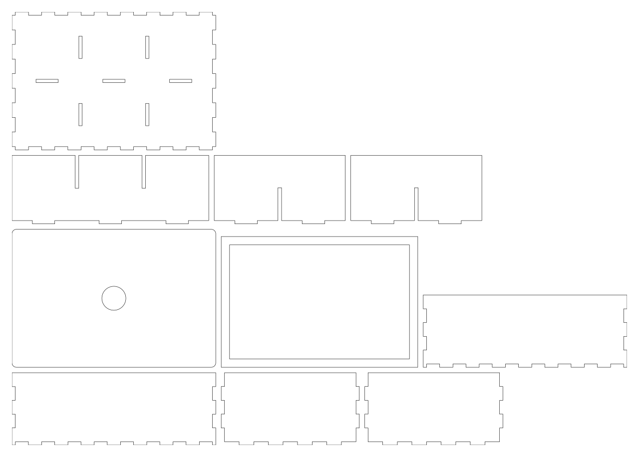
The same as commands. The first three lines are for the bracket lesson, its
sketch Profile and the ends of its extruded L, F2; the last is for the laser-cut box, whose set is
Cut sheet:
[
 ["file.export", {"path": "panel.dxf", "sketch": "Profile"}],
 ["file.export", {"path": "panel.svg", "face": "F2:endCap()"}],
 ["file.export", {"path": "parts.dxf", "faces": ["F2:endCap()", "F2:startCap()"], "gap": 5}],
 ["file.export", {"path": "box.svg", "set": "Cut sheet", "width": "600 mm", "gap": "8 mm"}]
]
gap and width are lengths like any other: 5, "5 mm" or "kerf * 4". feature.offsetProfile grows
a sketch by half the laser's kerf before you export it. DXF files are AutoCAD 2000 ASCII with their unit;
SVG files give their size in mm, cm or in, so they print and import at true size.
Cut lists: the plates of a design
A design built from panels (a shelf, a box, a cabinet) is cut from sheets. cut.list finds every body that
is a plate, a flat part of one thickness whose sides are square to its faces (holes straight through
are fine), and every sheet-metal part, by its flat pattern. It groups them by thickness and material
(body.material), gives each part its length × width (the smallest rectangle around it), its area and the
length of its cut, and counts the parts that are the same: the same outline and holes, however the body
lies in the model, also turned over. A body that is not a plate is listed under notPlates with the reason
and the face: a pocket's floor, a chamfer, a round on an edge.
cut.export writes the outlines to DXF or SVG at true size, each part in its own frame on a layer named
after it, a plate as seen from its top: of its two faces the one whose outward normal points most up, by the
first of its z, y and x that is not zero (so a plate standing upright with its front facing -y is drawn from its
far, +y face, the mirror image of file.export of the front face; the result's top names the face), a
sheet-metal part from its sketch's side: side by side on one sheet (width and gap as for a sheet of faces; it lays out in rows, it does
not nest), or one file per part ("layout": "each"). One of each part is drawn and the result says how many
to cut; "copies": true draws every body. kerf moves the cut off the part by that distance (half the width
the beam cuts away): the outline out, the holes in, the outside corners rounded as a round beam goes round
them. A kerf the beam cannot follow (a slot narrower than the beam) is refused with the largest that fits; an inner round smaller than the kerf comes out at the kerf's radius, as a sharp inner corner does, and the result says so.
A cut list: a small shelf
Two sides, a top and a bottom of 18 mm birch plywood, and a 6 mm hardboard back with a cable hole:
[
 ["feature.block", {"name": "Left side", "size": [18, 200, 300]}],
 ["feature.block", {"name": "Right side", "size": [18, 200, 300], "position": [582, 0, 0]}],
 ["feature.block", {"name": "Bottom", "size": [564, 200, 18], "position": [18, 0, 0]}],
 ["feature.block", {"name": "Top", "size": [564, 200, 18], "position": [18, 0, 282]}],
 ["feature.block", {"name": "Back", "size": [600, 6, 300], "position": [0, 200, 0]}],
 ["sketch.create", {"plane": "zx", "offset": 200, "name": "Cable hole"}],
 ["sketch.circle", {"sketch": "Cable hole", "center": [150, 150], "radius": 20}],
 ["feature.extrude", {"sketch": "Cable hole", "distance": 20, "symmetric": true, "cut": "Back", "name": "Back with hole"}],
 ["body.material", {"body": "Left side", "name": "birch plywood", "density": 680}],
 ["body.material", {"body": "Right side", "name": "birch plywood", "density": 680}],
 ["body.material", {"body": "Bottom", "name": "birch plywood", "density": 680}],
 ["body.material", {"body": "Top", "name": "birch plywood", "density": 680}],
 ["body.material", {"body": "Back", "name": "hardboard", "density": 900}],
 ["cut.list", {"format": "csv"}],
 ["cut.export", {"path": "shelf.svg", "copies": true, "width": "1250 mm", "gap": "10 mm"}]
]
The cut list (csv, ready for a spreadsheet; without format the same as JSON, with each part's frame in
the model):
material,thickness (mm),name,count,length (mm),width (mm),area (mm^2),cut length (mm),holes,kind,bodies,reason
hardboard,6,Back with hole,1,600,300,178743.3629385641,1925.663706,1,plate,Back with hole,
birch plywood,18,Left side,2,300,200,60000,1000,0,plate,Left side; Right side,
birch plywood,18,Bottom,2,564,200,112800,1528,0,plate,Bottom; Top,
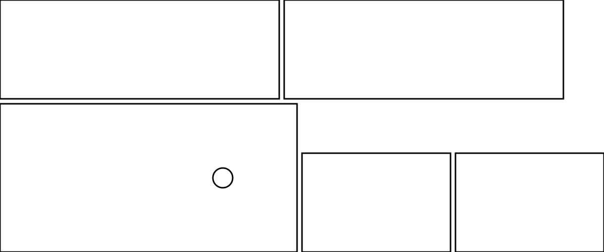
Drawings of the model as seen
All bodies exported as .dxf or .svg is a drawing of the whole model from a view: the
edges of the bodies and the outlines (silhouettes) of curved faces, with the lines behind a face left out
or drawn dashed.
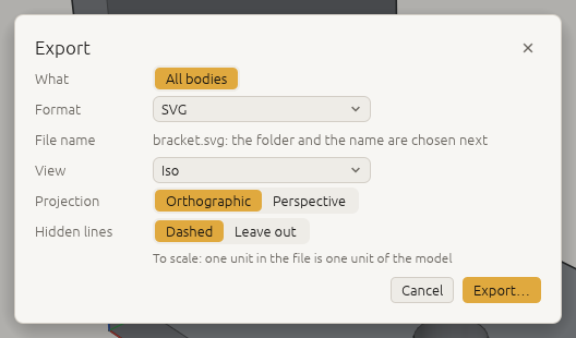
The export dialog asks:
- View: As in the viewport (what the window shows now), or Iso, Front, Back, Left, Right, Top, Bottom.
- Projection: Orthographic is to scale, one unit in the file for one unit of the model, so you can measure it; Perspective is for an illustration, true size only at the depth the camera looks at.
- Hidden lines: Leave out, or Dashed on a layer of their own.
It offers your last choice next time.
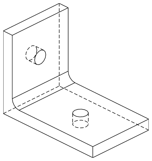
As commands:
[
 ["file.export", {"path": "bracket-front.dxf", "view": "front"}],
 ["file.export", {"path": "bracket-iso.svg", "view": "iso", "hidden": "dashed"}],
 ["file.export", {"path": "bracket-look.svg", "projection": "perspective"}]
]
From the command line: craft3d-cli convert bracket.3dcraft bracket-front.dxf --view front
(The command line and scripts).
The layers are visible, silhouette and hidden. Edges are written as the curves they are: lines,
circles and arcs (where they face the view), ellipses and elliptic arcs, splines; a circle seen edge on
is a line. The outlines of curved faces are fine straight pieces. The section and a rewound timeline are not applied: the drawing shows the whole model as it
is.
Files in the web version
The web version, 3dcraft.dev/app, reads and writes files on your computer; nothing is uploaded.
- Chrome, Edge and Chromebooks: Open…, Import…, Save As… and Export… show your system's file
dialog. Export… opens the same export dialog as on the desktop (what, the format, the options; the
format you used last is chosen), makes the file, and then shows the system's dialog to say where it
goes. Save writes back to
the file the document was opened from or last saved to; the first time, the browser asks whether the
page may change that file. If the file cannot be written, the document stays open and unsaved. An OBJ
with colours then offers its material file (
.mtl) with a Save… button: save it next to the.obj. - Firefox and Safari have no such dialogs for web pages: Save asks for a name in a small dialog of
its own, the export dialog has a File name field, and the file is a download (in the browser's downloads, often the Downloads
folder); Open and Import use the browser's file chooser. Add
?downloadto the address to work this way in Chrome too. - Drop a file on the page to open it (a
.3dcraft,.3dcraftjigor.3dcraftasm) or import it (a STEP file, a FreeCAD.FCStddocument or a.brepfile). - The status bar says where each file went (saved
part.3dcraft, downloadedpart.step: see the browser's downloads) or why it was not written. Closing a file dialog does nothing. - There is no autosave in the browser: a document lives in the page until you save it, and the browser asks before a page with unsaved changes is closed or reloaded.
Autosave and recovery
The desktop window autosaves documents with unsaved changes 30 seconds after a change, into a recovery
folder: 3dcraft/recovery in your state directory. That is ~/.local/state/3dcraft/recovery on Linux,
~/Library/Application Support/3dcraft/recovery on macOS and %LOCALAPPDATA%\3dcraft\recovery on
Windows; Help › Open data folder shows it on any system.
After a crash, the next start shows a bar with what was left: Recover, Discard (click twice: it
cannot be undone), Later. Closing the window normally asks, for each document with unsaved changes,
whether to save it, and then drops its autosave. An agent has the same with recovery.list,
recovery.open and recovery.discard, also in craft3d-cli serve and mcp when they are started with
--recovery-dir DIR.
Next: How 3DCraft thinks.