
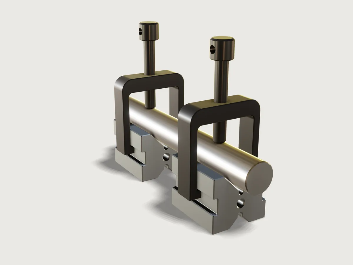
A matched pair of hardened and ground 90° V-blocks, the toolmaker's way to hold round work for inspection, marking out and drilling, in the common 45 × 40 × 35 mm size for shafts of 6 to 30 mm. Each block has a large and a small V with relief grooves at their apexes, side slots for its U-clamp, and an M6 tapped hole in each end; the black-oxide clamps hold a ground test pin with M8 tommy-bar screws. The pin is placed by the closed form for its height in a V, and the model proves the form right: the pin rests on both ground flanks of both blocks and enters neither.
What it shows
- One profile, drawn once.
sketch.pathdraws the whole cross-section with its two Vs, the round-bottomed relief grooves, the side slots with 0.5 mm radii in their inside corners and the 0.5 mm chamfers of the long edges;feature.extrudemakes the block, andfeature.chamferbreaks all 80 edges of its two end faces (the 40 sides of the profile, at both ends). - Tapped holes. A tap drill with its 118° point and a 90° countersink is one
feature.revolve;feature.mirrorcopies it to the far end of the block, twofeature.booleansubtractions drill both ends.feature.threadmarks each M6 hole, and the M8 holes of the clamps and the M8 screws, as ISO metric threads (cosmetic). - A matched pair by pattern.
feature.pattern(linear) makes the second block, the second clamp and the second screw, onepair_pitchalong the axis. - A named set.
set.definekeeps Tapped holes: the hole faces the two drills made, counted by an assertion and kept by the document as the design changes. - Contact as a proof. The pin is placed by the closed form;
measure.distanceto each bounded flank face andoverlapprove that it touches all four flanks without entering a block (below). - References by feature name. Faces are named after the features that made them
(
Two blocks:copy(0)/Block blank:startCap), and the checks find faces withmadeBy, so they hold whatever feature ids the history gives. The edge ids of the profiles (side(e33),side(e42)…) come from their sketches and are pinned there: redraw a profile and read them again. - Drawings.
file.exportwrites the end, side and top views as SVG to scale, hidden lines dashed in the end and side views, and the exact geometry as STEP. - Outputs.
variable.measurereports the mass of the two blocks and the height over the pin, the measure a toolmaker takes with a height gauge.
The real thing
- Reference. The blocks follow Haas Tooling's 09-0550 V-block and clamp set: 45 mm long, 40 mm wide, 35 mm high, 90° V, for work of Ø 6 to 30 mm; a V 25 mm wide and 14 mm deep and a secondary V 15 mm wide and 9 mm deep, clamp slots 10 mm wide; 40Cr steel hardened to 52–58 HRC, the V flat to 0.003 mm, parallel within 0.01 mm. The model reads the two depths as the V's own (12.5 and 7.5 mm for a 90° V of those widths) plus a relief groove 1.5 mm below the apex. Other makers sell the same type at about this size: Holex (Hoffmann Group) 447010, 50 × 40 × 40 mm for Ø 5 to 30 mm (data sheet), and STEINLE model 6503, 40 × 35 × 35 to 70 × 63 × 44 mm (data sheet).
- This example's own sizes. Haas gives no more than the above, so these are chosen, and stated: relief grooves 3 mm wide with a round bottom; slots 3 mm deep, centred on the height, so the clamp hooks in with either V on top; 0.5 mm radii in the slots' inside corners; 0.5 mm chamfers on the outer corners, the slot and V mouths and all round both end faces; an M6 tapped hole in the middle of each end face (tap drill Ø 5 mm, ISO 2306), 14 mm deep at full diameter with a 118° point, 90° countersink to Ø 6.4 mm, threaded 10 mm, which leaves 4 pitches below the thread for a plug tap's lead; it is for bolting the block to an angle plate or a fixture. The hole sits midway between the two apexes, 15 mm up. Its bore leaves 3.5 mm to each relief groove; the thinnest wall round it, 2.30 mm, lies at the end face, between the countersink and the end chamfer of the top relief groove.
- The clamps. Cut from 14 mm steel plate: legs 5 mm thick, 0.5 mm clear of the block's sides, with hooks 6 mm high that reach into the slots to 0.5 mm from their bottom and bear up against the slots' upper face; a crossbar 10 mm thick whose underside lies 3 mm above the largest pin (Ø 30 mm); corner radii of 3 mm inside and 8 mm outside; drilled Ø 6.8 mm (ISO 2306) and tapped M8 × 1.25 (ISO 261) through the middle of the crossbar. The screw is M8, 50 mm from its tip to its head, with a flat tip chamfered 1 mm, a Ø 14 × 12 mm head and a Ø 5 mm cross hole for a tommy bar; its full thread stops 3.2 mm under the head, the normal run-out x max of ISO 3508 for M8. Its tip bears on the pin.
- The test pin. A ground pin of the Pin diameter, as long as both blocks and the 40 mm between them plus 15 mm at each end, its ends chamfered 0.5 mm.
- Why the relief grooves. The wheel grinds each flank over its whole width without having to reach a sharp apex, and burrs or dirt in the corner cannot hold the work off the flanks.
- Making it. The blocks are milled from bar along their length (the Vs with an angle cutter, the slots and grooves with formed cutters), drilled and tapped at the ends, hardened and tempered, then ground as a pair on every face so that both stand at the same height. The clamps are cut from plate (laser or waterjet), drilled, tapped and black oxided; the screws are turned, cross drilled, rolled and black oxided. The two blocks weigh 0.778 kg in steel; Haas lists 0.8 kg for its set.
- Simplified, or left out.
- The threads are cosmetic: the holes are drawn at their tap drill and the screws at their major diameter, as drawings show threads, so each screw overlaps its clamp by the thread's depth (the checks leave that pair out).
- No matched-pair numbers are engraved on the blocks, and the screws have no swivel pad.
- The test pin stands for the work; a real set is sold without it.
Parameters
| Parameter | Range | Default | What it does |
|---|---|---|---|
| Pin diameter | 6 to 30 mm, step 1 mm | 20 mm | the pin in the large Vs; it rises by d/√2 + d/2 at its top, and the screws follow it down |
| Block length | 40 to 100 mm, step 5 mm | 45 mm | each block's length along its V; the clamps stay at the blocks' middles and the pin grows with them |
Checks
- Block section in closed form. A block cut at its middle must have the area B·H − (W₁² + W₂²)/4 − (2 + π)/4·g² − 2·s·h + (4 − π)·r² − (4 + √2)·c²: the rectangle, less the two 90° Vs (W₁ = 25, W₂ = 15), the two round-bottomed relief grooves beyond them (g = 3), the two slots (s = 3 deep, h = 10 high), plus the four inside radii (r = 0.5), less the eight 45° chamfers and the four chamfers at the V mouths (c = 0.5). It is 1114.79246 mm², exact to 0.000001 mm².
- Pin centre r√2 above the apex. The pin's centre of mass lies
top_apex_z + d/√2up: 36.6421356 mm at Ø 20 mm (26.7426407 mm at Ø 6, 43.7132034 mm at Ø 30). The height over the pin is 46.6421356 mm. - Pin on both flanks of both blocks. Four checks: the distance from the pin to each top flank of each block is at most 0.000001 mm (8.2 × 10⁻⁹ mm found). The flanks are bounded faces that stop at the relief groove and at the mouth chamfer, so the pin touches the ground flank itself. With the next check this proves the closed form: a pin placed 0.01 mm higher fails all four (0.00707 mm), and so does a pin too large for the V (Ø 36 mm: 0.0188 mm, it would sit on the mouth chamfers) or too small (Ø 4 mm: 0.00368 mm, it would sit on the groove's edges).
- Blocks, clamps and pin do not overlap, and screws overlap neither pin nor blocks.
- Screws bear on the pin. Distance 0 mm.
- Clamp hooks bear on the slots. The hooks' tops lie on the slots' upper faces: distance 0 mm.
- Pin clear of the clamps. At least the 3 mm headroom: 10.5 mm at Ø 20 (to the legs), 15.0069431 mm at Ø 6, 3 mm at Ø 30 (to the crossbar).
- Screw heads clear of the crossbars. At least 1 mm: 24.9289322 mm at Ø 20, 8.02943725 mm at Ø 6, 37 mm at Ø 30.
- Six tapped holes. The named set Tapped holes holds four M6 holes in the blocks and two M8 holes in the clamps.
- Walls round the tapped holes at least 2 mm. The distance from every face the tap drills made (countersink, bore and point) to every other face of the blocks but their end faces: 2.30 mm found (at least 2.05 mm proven), at the countersink's rim beside the end chamfer of the top relief groove (the bore itself is 3.5 mm from the groove).
craft3d-cli check-range proves all fourteen at 13 points: the defaults, the four corners of the two
ranges (Ø 6 and Ø 30 with 40 and 100 mm blocks) and eight random points.
The README in the model's repository has the rest (Files, Rebuild, Difficulty, Platform notes, Licence): the whole README on GitHub.