
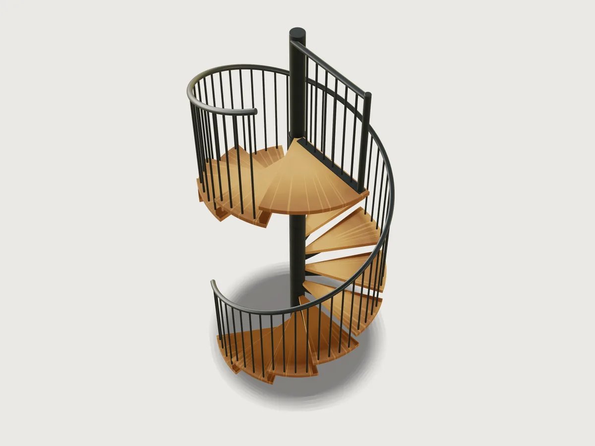
A steel spiral staircase with oiled oak treads for a house: 15 risers of 186.67 mm from floor to floor at 2800 mm, Ø 1600 mm, round a Ø 114.3 mm column, each oak tread on a steel T-carrier stacked between spacer tubes, with a handrail swept along a helix, a balustrade of round bars and a landing with its own guard. The stair works itself out from two numbers, the floor-to-floor height and the diameter: how many risers, how many treads to a turn, where the walking line runs and how wide the landing may be, all by formulas from DIN 18065's rules. It proves the result with a 2000 mm headroom gauge standing on every tread, the stair rule at the walking line, the railing's gaps and closed forms of the oak, at every one of the parameters' 119 combinations.
What it shows
- The stair worked out by formulas.
variable.setturns the two parameters into the stair a designer would draw:- Risers. With twelve treads to a full turn, the tread above a nosing is eleven risers up (the tread a
turn up reaches over it by the nosing overlap). So the rise must be at least (2000 + 40) / 11 =
185.45 mm for 2000 mm of headroom under a 40 mm tread, and the height is split into the most risers that
keep it so:
floor(floor_to_floor / rise_for_headroom). The landing is the top step, so there is one tread less than risers. - Walking line. The usable width runs from where the going is 50 mm (95.49 mm from the axis at 30°) out to the inside of the handrail. DIN 18065's walking area is the two tenths of it that start at its middle, and the walking line runs in the walking area's middle, at 60 % of the usable width.
- Treads per turn. Twelve, or more on a wide stair: the whole number that brings the going on the walking line nearest to 630 mm less two rises, the stair rule's ideal.
- Landing. As many tread angles wide as keeps 2000 mm of headroom over the treads under it, at most a quarter turn.
- Risers. With twelve treads to a full turn, the tread above a nosing is eleven risers up (the tread a
turn up reaches over it by the nosing overlap). So the rise must be at least (2000 + 40) / 11 =
185.45 mm for 2000 mm of headroom under a 40 mm tread, and the height is split into the most risers that
keep it so:
- A handrail along a helix.
datum.helixfollows the treads' screw (one turn rises twelve risers; its height is the fourteen treads' rise).datum.planethrough three points lays the profile square to the helix at its start, andfeature.sweepwith the helix aspathcarries a 42.4 × 2.6 mm tube along it (two circles: the inner one is the bore). A plug drawn on the start plane is copied to the far end by afeature.patternthat turns and lifts it as the helix does. - Screw patterns.
feature.patternwithangleandstepturns each copy one tread angle and lifts it one rise: once for the treads, once for their steel carriers, once for the rows of balusters and once for the hidden headroom gauges; a plainstepstacks the spacer tubes, each one revolved section with its centring rings. Inside a tread the balusters (four at the defaults) are a screw pattern of their own (each a share of the tread angle and of the rise), so each one's top meets the rising handrail the same way; a level cut (feature.booleansubtract of a block) then gives them all the same foot under the tread. The number of balusters per tread is a formula of the 100 mm gap. - A T-section carrier. On a
datum.planethrough three points at the bracket's root (x out along the tread, y up),sketch.pathdraws the 10 mm blade, its tip rounded R10 by an arc whose centre and tangent point are formulas of the blade's length and depths, so it stays tangent whatever the diameter; a 60 × 8 mm flat on the same plane is welded on top, and asketch.patterngrid drills it for four screws into the tread. - Revolved sectors. A tread and the landing are rectangles in a radial plane turned about the column's
axis by
feature.revolvewith anangle, so their arcs are exact cylinders about the axis whatever the parameters (see Platform notes for why not sketched arcs).feature.filletrounds all eight edges of their top and bottom by 3 mm;feature.chamferbreaks the collars' edges and the base plate's. - Baluster tops cut to the rail's slope. The first baluster is cut by a datum plane through three points that holds the helix's tangent, 0.5 mm under the rail, before it is patterned: the cut follows every copy.
- A landing guard on a line parallel to its edge. The landing has a T-carrier like a tread's under
its first tread angle and a second carrier, a 60 × 8 mm flat, along the guard line:
feature.booleansubtract withkeepToollets it into a groove in the landing's underside, so it costs no headroom. The guard's base flat, balusters (sketch.patternwith astep) and post stand on a line 45 mm inside the landing's back edge; its rail, afeature.cylinderless a bore, is coped round the column by subtracting a cylinder 0.5 mm over it, and a bore cut from the post leaves it a capped tube. - Headroom proved by gauges. A 2000 mm tall gauge over the walking area stands on the lower floor in
front of the first tread, and the screw pattern stands a copy on every tread (15 in all).
assert.addwithoverlapproves that none reaches into a tread, a carrier, the landing or its carriers.feature.visiblehides them. - Materials.
material.presetsteel, coloured anthracite and made a dielectric (metallic 0, roughness 0.45) for the powder coat, on every steel body; oak for the treads and the landing. A body has one wood frame (F-083), and the fourteen treads turn round the column, so the oak's pattern has its pith on the column's axis: its medullary rays then run out from the column along every tread, as a tread's grain runs, and its rings are drawn 900 mm apart, wider than a tread. - Outputs.
variable.measuregives a tread's plan area, the treads' oak volume, the column tube's section and the masses of oak and steel;variable.outputthe step measure, the headroom, the column's mass per metre, the balusters' lengths and the handrail's length.
The real thing
-
Which stair. A Ø 1600 mm spiral stair has 653 mm of usable width: less than the 800 mm DIN 18065 asks of the stair a house must have, so it is the second stair, one building law does not require: to a gallery, a loft or an upper room within a dwelling. For it DIN 18065:2020-08 (Table 1, buildings with no more than two dwellings and within dwellings, stairs not required by building law) asks a usable width of at least 500 mm, a rise of 140 to 210 mm and a going of 210 to 370 mm (as tabulated by heimwerker.de and Baunetz Wissen, Auftritt), and the step measure 2 s + a must lie between 590 and 650 mm, 630 mm being the ideal (Baunetz Wissen, Steigungsverhältnis).
-
Walking line and headroom. On a stair up to 1000 mm wide the walking area is two tenths of the usable width, starting at its middle; the going and the step measure are taken on the walking line within it, and the clear headroom of at least 2000 mm is measured upright over the walking area (Baunetz Wissen, Spindeltreppen). On a winding tread the usable width stops where the going falls under 50 mm in a house (100 mm in other buildings; Baunetz Wissen, Auftritt). Open stairs get a nosing overlap of at least 30 mm (Baunetz Wissen, Stufen).
-
Railing. 900 mm high over the nosings and over the landing, the German building codes' guard height for a fall of up to 12 m (TÜV SÜD, Geländer), with no gap between bars a 100 mm sphere can pass. That meets the strictest of the common rules: the 100 mm sphere of the UK's Approved Document K for guarding in dwellings (NHBC, Guarding to treads and risers), the 4 in (101.6 mm) sphere of the US IRC R312.1.3 (Jaspector, IRC 2021) and the 120 mm of the German state building codes, which bind only buildings with more than two dwellings (TÜV SÜD, above). The open risers do not: see below.
-
Steel. Tube sizes from EN 10220 (as tabulated by pipeflowcalculations.com for DN 100 and DN 125): the column 114.3 × 4.0 mm (10.9 kg/m), closed by an 8 mm disc welded flush into its top; the spacers 139.7 × 6.3 mm, centred on the column by a 10 mm ring bored Ø 115.3 mm welded into each end; the handrail and the landing guard's rail 42.4 × 2.6 mm; the guard's post 48.3 × 2.6 mm, capped 4 mm. The collars are 100 mm lengths of 139.7 × 12.5 mm tube bored to Ø 115.3 mm (1 mm over the column), a 12.2 mm wall that takes an M12 set screw, so collars and spacers give the column one outside diameter. Ø 16 mm round bar for the balusters; the carriers a 10 mm blade under a 60 × 8 mm flat drilled Ø 7 mm for four screws; a 15 mm base plate with four Ø 18 mm anchor holes on a Ø 230 mm circle; a 60 × 8 mm flat under the guard, on which its post stands whole and closed. Steel S235, powder coated anthracite grey: RAL 7016, drawn with #293133, the screen value most often given for it.
-
Oak. European oak treads 40 mm thick, glued up from staves with the grain running out from the column, CNC-routed to the sector, drilled Ø 17 mm for the four balusters, the edges of top and bottom rounded 3 mm, oiled. Density 750 kg/m³ (the preset's).
-
The stair at the defaults (
output.list,variable.set):Risers 15 of 186.67 mm: 14 treads and the landing Treads to a turn 12, at 30°; each tread spans 33.53° with its nosing overlap Usable width 653.31 mm, from 95.49 mm to 748.8 mm from the axis Walking area, walking line 422.15 to 552.81 mm from the axis; walking line at 487.48 mm Going at the walking line 255.24 mm; step measure 2 s + a = 628.58 mm Headroom behind a nosing 2013.33 mm Landing 60°, the stair turning 480° from the first nosing to the landing's back edge Balusters 4 per tread, 56 on the stair, 84.72 mm apart in the clear; 936.11 to 1076.11 mm long at their axes Handrail 6220.02 mm along its centre line, on a helix of radius 770 mm and pitch 2240 mm Landing guard 6 balusters and a post, 82.98 mm apart in the clear, 97.33 mm from the column Oak 87.24 kg (treads 77.53 kg, landing 9.71 kg) Steel 340.97 kg: carriers 128.39, balusters 88.93, column 49.14, spacers 31.09, handrail 15.87 (plugs 0.05), landing guard 15.33, landing carriers 12.17 -
Making it.
- Cut the column to length, weld on the base plate and the flush cap disc (nothing stands out beyond
the tube's Ø 114.3 mm); drill the anchor holes. Cut the collars from 139.7 × 12.5 mm tube, bore them
to Ø 115.3 mm and tap each for an M12 set screw; laser-cut the blades
(
exports/spiral-staircase-bracket.dxf) and the flats, weld each T-carrier to its collar and drill its flat; cut the spacers to the rise less the collar (86.67 mm, the bottom one 31.67 mm) and weld a centring ring into each end. Cut the balusters to their four lengths and the guard's parts. Bend the handrail tube on the helix (radius 770 mm, pitch 2240 mm): 6.22 m long, it is bent from a 12 m length, or from two 6 m lengths spliced at a baluster. Powder coat everything. - Rout and drill the oak treads and the landing, round their edges, rout the landing's groove for its flat, oil them.
- On site: anchor the base plate and stand the column. Slide on from the top the bottom spacer, then carrier and spacer in turn, each carrier turned one tread angle on from the one below and fixed with a set screw: the stack of spacers and collars sets the rises and carries the treads down to the base plate. Screw each tread to its carrier's flat from below.
- Fit the balusters through the treads and nut them underneath; lay the handrail on them and weld it. Fit the landing on its carrier and its let-in flat, fix its outer edge to the upper floor, bolt the guard's post through the landing into the flat and weld the guard's rail to the column. Welded on site after powder coating, the handrail's and the guard rail's joints need a touch-up of the coat.
- Cut the column to length, weld on the base plate and the flush cap disc (nothing stands out beyond
the tube's Ø 114.3 mm); drill the anchor holes. Cut the collars from 139.7 × 12.5 mm tube, bore them
to Ø 115.3 mm and tap each for an M12 set screw; laser-cut the blades
(
-
Simplified, or left out.
- No fixings: the anchor bolts, the collars' set screws, the screws under the treads, the nuts under the balusters, the post's bolts and the welds are not drawn. The balusters stop 0.5 mm under the handrail (the weld) and pass through their holes 0.5 mm clear.
- The landing's outer edge is fixed to the upper floor's edge, which is not drawn, nor is the floor opening.
- The risers are open: 146.67 mm between a tread's top and the next tread's underside. That passes a 100 mm sphere, which Approved Document K forbids in dwellings (NHBC, above), and is more than the 120 mm DIN 18065 allows in non-residential buildings; there a riser bar under each nosing is needed.
- The handrail's ends are cut square to the helix and closed by a 3 mm disc set half into the tube, not rounded (see Platform notes).
- The tread's plan corners are square: a corner rounded into the outer arc cannot be rounded over (see Platform notes).
- The wood is a procedural pattern with one frame for all treads (F-083), its rays standing for the long grain.
- No structural calculation: the loads on the cantilevered treads, the collars and the column are not checked.
Parameters
| Parameter | Range | Default |
|---|---|---|
| Floor to floor | 2400 to 3200 mm, in steps of 50 mm | 2800 mm |
| Diameter | 1400 to 2000 mm, in steps of 100 mm | 1600 mm |
Over the 119 combinations of their steps the stair has 12 to 17 risers of 185.71 to 200 mm, takes 12 to 17 treads to a turn and 3 or 4 balusters to a tread, and its landing is 60° to 90° wide. The going at the walking line runs from 222.65 to 266.15 mm, the step measure from 595.26 to 638.31 mm and the headroom behind a nosing from 2002.86 mm up; the usable width from 553.31 mm (Ø 1400 mm) to 829.43 mm (Ø 2000 mm).
Checks
Sixteen assertions, all passed at the defaults. craft3d-cli check-range passed them at 13 points (the
defaults, the four corners and 8 random points), and all 119 combinations of the two parameters' steps,
set one after another with param.set, passed document.check.
- One tread per riser below the landing: the treads' top faces number
tread_count(14). - First tread one rise up, last tread one rise below the landing, landing level with the upper floor: the treads' box starts at rise − 40 mm and ends at floor to floor − rise, and the landing's top is at floor to floor, to 0.001 mm. With the screw pattern's step, every riser is the same.
- Rise, going and usable width within DIN 18065: 186.67 mm in 140 to 210 mm, 255.24 mm in 210 to 370 mm, 653.31 mm at least 500 mm. These are the formulas the geometry is built from.
- Stair rule at the walking line: 2 s + a = 628.58 mm, between 590 and 650 mm.
- Headroom over the walking area: none of the 15 gauges, 2000 mm tall over the walking area from 1 mm behind a nosing to 1 mm before the next (at the walking area's inner edge), overlaps the treads, their carriers, the landing or its carriers. The flat landing is nearest the treads under its back edge, which are two risers higher than those under its front; the gauges standing there are checked against it too.
- No part runs into another: the column, spacers, treads, carriers, balusters, landing, its carriers and its guard have no volume in common.
- Baluster gap on the stair (84.72 mm), on the landing (82.98 mm) and at the column (97.33 mm): at most 100 mm, measured between the bars' faces. Over the 119 combinations they run from 71.64 to 99.87 mm, 75.84 to 83.21 mm and 90.48 to 97.55 mm.
- Tread outline in closed form: a tread's section at mid-thickness is the sector, (span / 2)(R² − r²), less the four holes, to 0.01 mm²: 184784.21 mm².
- Oak of the treads in closed form: the fourteen treads hold the plan area times 40 mm less the round-overs: on each of the eight edges a fillet's section (1 − π/4) ρ² swept along the edge (Pappus on the two arcs, at the section's centroid, (10 − 3π)/(12 − 3π) ρ from the faces), less a centroid's distance at each of the mitred corners: 103 373 180 mm³, within 0.1 mm³ a tread (the mitres where an arc's round-over meets a straight one are curves, not planes; measured, the difference is 0.035 mm³ a tread).
- Column tube to EN 10220: the tube's section, 1386.07 mm², at 7850 kg/m³ weighs 10.881 kg/m, 0.18 % under the standard's 10.9 kg/m (allowed: 0.5 %).
Not asserted: the handrail's position and the baluster tops' clearance under it. Both are placed by the formulas, but the measures on the swept tube are slow or not proven (Platform notes).
The README in the model's repository has the rest (Files, Rebuild, Difficulty, Platform notes, Licence): the whole README on GitHub.