
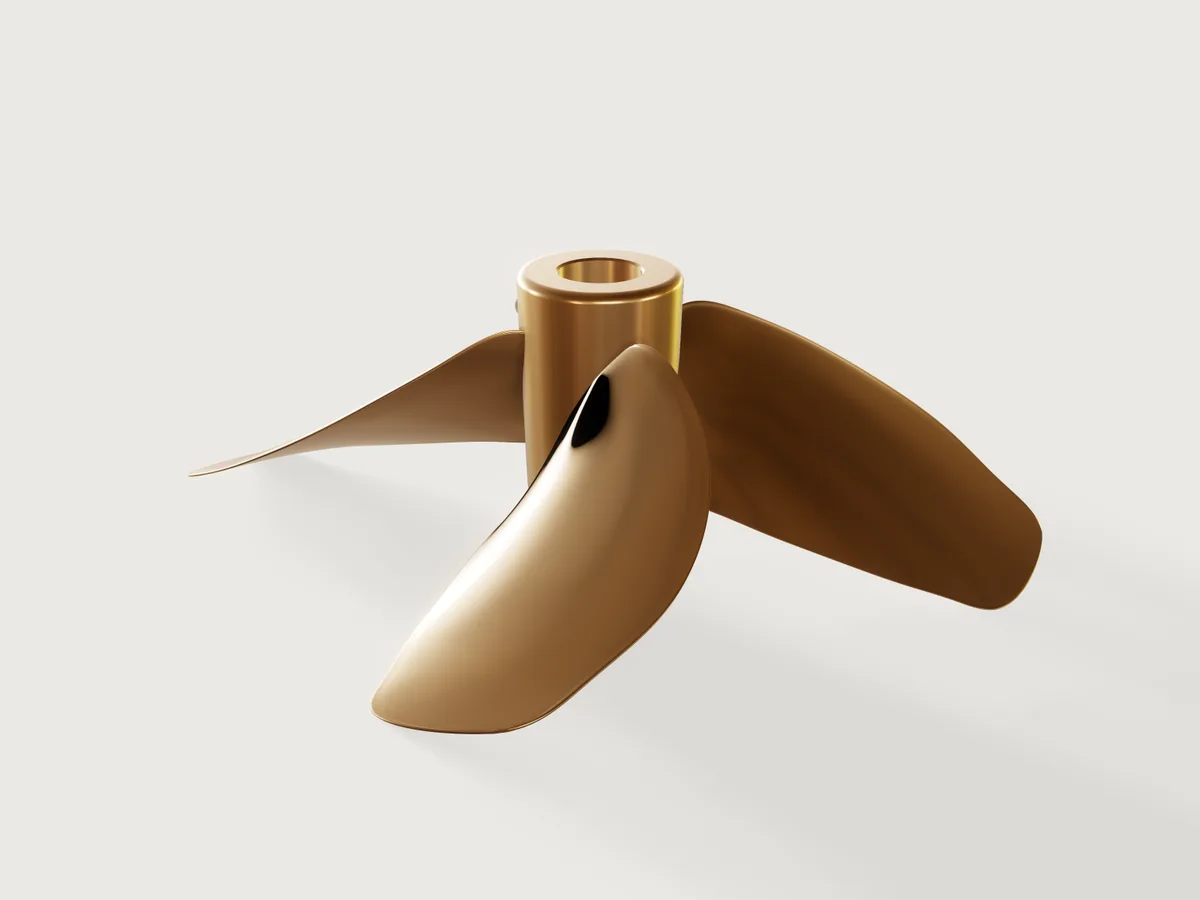
A four-blade fixed-pitch ship propeller of the Wageningen B-series, the systematic series ship designers have chosen propellers from since the 1930s: a B4-55 of Ø 600 mm, pitch ratio 0.8 and 15° rake, cast in nickel-aluminium bronze and bored to a 1:10 taper for a 50 mm shaft. From 0.2 R to the tip the blade follows the series' published tables (outline, thicknesses and the section ordinates themselves), and the model proves its expanded area ratio, its sections, its mass, its hub and its balance. Diameter, pitch ratio and the series member (B4-40, B4-55, B4-70) are parameters.
What it shows
- A published series as a table.
table.setholds the B-series of Oosterveld and van Oossanen (1975) for r/R 0.2 to 1.0: Table 1's chord factor, the distances of the generator line and of the thickest point from the leading edge (a/c, b/c), the thickness coefficients A and B (t/D = A − B·Z), Tables 2 and 3's ordinates V1 and V2 at the stations used, and the integrals of V2 that the checks use. - Sections from the series' formulas. Every section but the small round tip is a closed
sketch.splinewithlive: truethrough 18 points whose coordinates are formulas of the table: the face at V1·(t − te) and the back at (V1 + V2)·(t − te) + te above the pitch line (the paper's equations 2 and 3), the edges rounded off. - Expanded sections placed on the blade. Each section lies on a
datum.planethrough three points: the point of the generator line at its radius r (raked 15° aft), a point along the chord turned from the plane of rotation by the pitch angle atan(P / 2πr), and one towards the back. - A loft and a pattern.
feature.loftthrough eleven sections makes one blade;feature.patternsets four round the shaft. - A turned and keyed hub. One revolved half section (
feature.revolve) with the forward recess and the 1:10 taper bore,feature.filleton its ends,feature.chamferon the bore's mouths, a keyway cut along the taper (feature.extrudewithcut), joined to the blades withfeature.boolean. - Helpers for cheap, exact checks. The union keeps the hub as a body of its own (
keepTool), afeature.transformkeeps a copy of one blade, and the expanded blade outline is drawn from the table as on a propeller drawing; all three are hidden (feature.visible), and so is the outline's sketch, which lies below the propeller and would otherwise widen the view it opens in. Cutting them costs a fraction of cutting the whole propeller. - Material, outputs and checks.
material.presetandbody.material(nickel-aluminium bronze, its density a variable);variable.measureandvariable.outputfor the mass and the expanded area ratio;assert.addfor the checks below.
The real thing
- The series. M. W. C. Oosterveld and P. van Oossanen, Further computer-analyzed data of the Wageningen B-screw series, International Shipbuilding Progress 22 (251), 1975 (NSMB publication 479): Table 1 (dimensions of the four- to seven-bladed series), Tables 2 and 3 (V1 and V2), equations 2 and 3 (the section's face and back).
- Outline and thickness. At each r/R the chord is c = factor · D · (AE/A0) / Z, the leading edge lies a/c · c ahead of the generator line, the section is thickest b/c · c behind the leading edge, and its thickness is t = (A − B·Z) · D. At the defaults the root (0.2 R) is 137.1 mm long and 21.96 mm thick.
- Sections. Back (V1 + V2)·(t − te) + te, face V1·(t − te), with P = 1 at the leading edge, 0 at the thickest point, −1 at the trailing edge. The spline passes through the back at P = ±0.95, ±0.8, ±0.4 and 0, the face at ±0.95, ±0.6 and 0, both edges and the edges' rounds, so the inner sections keep the series' raised face edges (V1) and the outer ones their flat face and nearly circular back. The paper leaves the edge thickness te to the classification society and the foundry; here it is the series' own tip thickness, 0.0030 D (1.8 mm), rounded off.
- What the table does not give. Inside the hub a section at 0.75 of the hub's radius: the 0.2 R section scaled until it lies 2 mm inside the hub (to 0.712 of it at the defaults, its chord turned to the pitch angle there, 63.9°), so the blade root runs into the hub and the union finds where it meets it. Near the tip a section at 0.975 R: the outline between 0.9 R and the tip continued as a parabola, c ∝ √(1 − r/R) (chord factor 0.791), the thickness falling linearly to the series' 0.0030 D at the tip; the leading edge kinks slightly there. At R a small rounded end, 4 te long and te thick.
- The root narrows at the hub. A flat section on the plane that touches its cylinder at r reaches out to √(r² + w²), where w is how far it reaches across the blade (its chord turned to the pitch angle, and its thickness); the section that must lie 2 mm inside a hub of D/6, at 0.75 of the hub's radius, is therefore the series' 0.2 R section scaled to 0.712, and the loft narrows towards it. Cut in planes square to the blade, the blade has 2076.5 mm² at 0.2 R but 1789.8 mm² at the hub's radius (13.8 % less), and its least second moment falls from 58 285 to 45 094 mm⁴ (22.6 % less): the most loaded section is the weakest, with a sharp corner where it meets the hub. On the real propeller the pattern maker fills the blade roots into the hub by hand (wax or filler on the pattern, as foundries do), which makes the root fillets and restores the section; this model has neither.
- Placing the sections. The series' sections are expanded: drawn flat, each belongs wrapped onto its cylinder. 3DCraft lofts flat sketches only, so each lies on the plane that touches its cylinder at the generator line, and away from that line it leaves both the cylinder and the pitch helicoid. The leading edge of the 0.2 R section stands 19.56 mm off its cylinder and 11.80 mm forward of the helicoid: the helix through it has a pitch of 583.4 mm, 21.5 % more than the 480 mm of the face. At 0.7 R the leading edge stands 17.35 mm off and 1.65 mm forward (506.4 mm, 5.5 % more). The sections are the series', but the blade's edges lie further from the shaft, and its outline seen along the shaft is wider, than on a blade whose sections are wrapped.
- Pitch and rake. The face pitch is P = 0.8 D = 480 mm at every radius, exactly so on the generator line and less so towards the edges (above); the four-blade members of the series have a pitch reduced towards the root, which is left out. The generator line is raked 15° aft. The propeller is right-handed: seen from aft it turns clockwise going ahead.
- Hub and shaft. The hub is Ø D/6 = 100 mm at its aft end, the series' boss: the series' chord factors integrate to π/2, the expanded area of the nominal ratio, from r/R = 1/6 (to within the 0.2 % the area check finds). The boss widens forward at a 2° draft, so its pattern draws from the sand (about Ø 104 mm where the blades meet it, Ø 111 mm at its forward end; the root cut "at the hub's radius" lies just inside it). It is long enough that the 0.2 R section's full chord and thickness, turned to the pitch angle at 0.75 of the hub's radius (the steepest the root gets), stay inside it by the end rounds and 5 mm: 158.5 mm. That the root stays inside is by this construction, not asserted: a cut of the blade costs load time, and at the aft end the raked outer blade passes the hub's plane far out. The bore is the metric 1:10 taper of ISO 4566 as propeller makers list it for a 50 mm shaft (an example): 120 mm long, Ø 50 mm to Ø 38 mm at the aft face, where the nut bears. Forward of it a relief counterbore of Ø 56 mm (3 mm clear of the shaft all round), 38.5 mm deep, takes up the length the blade root needs beyond the taper. The keyway is for a DIN 6885-1 key 14 × 9 (shafts over 44 to 50 mm): 14 mm wide and 3.8 mm deep in the hub, along the taper. The hub's ends are rounded D/96, the bore's mouths chamfered 1.5 mm.
- Material and making. Nickel-aluminium bronze CuAl10Fe5Ni5-C (EN 1982, CC333G), 7.6 g/cm³, a usual alloy for cast propellers: sand cast, the blades ground and polished, the bore turned to the taper and the keyway slotted, then balanced. Mass at the defaults: 19.23 kg.
- Left out. The root fillets that join a real blade to its hub (3DCraft refuses them here, see Platform notes; the narrowed root above is what that leaves), the B4 series' root pitch reduction, the boss cap and the nut, and the manufacturing tolerances of ISO 484-2 (for Ø 0.8 to 2.5 m, so only the top of the range).
Parameters
| Parameter | Range | Default |
|---|---|---|
| Diameter | 500 to 800 mm, in steps of 50 mm | 600 mm |
| Pitch ratio P/D | 0.6 to 1.2, in steps of 0.05 | 0.8 |
| Expanded area ratio | 0.40, 0.55 or 0.70 (B4-40, B4-55, B4-70) | 0.55 |
The bore stays that of a 50 mm shaft over the whole range.
Checks
- Expanded area ratio of the series member. Four times the area of the expanded blade outline, drawn from the table from the hub's radius to the tip, over the disc's area πR²: 0.5492 against the nominal 0.55, within 2 %.
- Four blades. The propeller has four blade tips.
- Blade from its root section to the diameter. The blade (its hidden copy) cut along its generator line reaches from its root section in the hub to the tip: 262.5 mm, R less 37.5 mm, so the propeller is Ø 600 mm.
- Section at 0.7 R as the series' ordinates. The blade's copy cut in the plane of its 0.7 R section has 1227.44 mm²; the series gives 1229.33 mm²: (t − te) times the chord before and after the thickest point, each times the integral of V2 over it (Simpson's rule over Table 3), plus te times the chord and the edges' rounds. Within 2 %.
- Bronze mass as the hub and four series blades. 19.234 kg against 19.132 kg for the hub (measured on its own) and four blades whose volume is Simpson's rule over the series' section areas from 0.2 R to 0.8 R, trapezoids from there to the tip and across the narrowed root; within 3 %.
- Hub at its aft end: bore, taper and keyway. The hub cut one and a half end rounds in from its aft face is exactly the closed form, 6707.21 mm²: its disc at that point of the 2° boss, less the bore at that point of the 1:10 taper, less the keyway (the 14 mm strip up to its 3.8 mm depth, less the circle segment that is bore already).
- Hub at its forward end: counterbore. Likewise at the forward end: the disc less the Ø 56 mm counterbore, 7112.10 mm².
- Boss drawn from the mould.
measure.draftof the boss, pulled aft: at least 2° (2.000°, proven). - Balanced about the shaft axis. The centre of mass lies 0.066 mm off the axis along x (the keyway's side) and on it along y, within a limit of 0.25 mm chosen here (not a figure of ISO 484-2); the foundry balances the finished propeller statically in any case.
craft3d-cli check-range proves all of them at the defaults, the eight corners of the parameter box
and random points in it (tools/examples.py check).
The README in the model's repository has the rest (Files, Rebuild, Difficulty, Platform notes, Licence): the whole README on GitHub.