
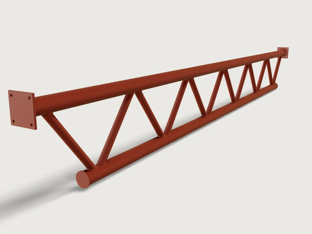
A 6 m Warren truss of round steel tubes, of the kind that carries a canopy or a mezzanine roof: two EN 10219-2 hollow-section chords, twelve diagonals with no verticals, gap K-joints set out to EN 1993-1-8, and end plates that bolt to the supports. Each diagonal is coped by subtracting the chord's outside cylinder from it, so it sits on the chord with no root gap, and is fillet-welded all round with a weld sized for full strength. Every diagonal is the same part, and its coping template is the coped tube laid flat. The truss checks its own set-out against the code's validity ranges and its steel against closed forms.
What it shows
- A standard's sizes in a table.
table.setholds four pairs of EN 10219-2 sections (chord and diagonal) with their tabulated masses;variable.publishwithchoicesFrommakes them the Section pair choice. Span, Depth and Panels are public too; the depth's range is a formula of the span, and the panel count's range a formula of both, chosen so that the diagonals set out on the chord axes lean 30° to 55°. - The joint set-out in formulas. The diagonals' angle is solved in closed form (
atan2andasin) from the span, depth, panel count, the sections and the weld size; the gap and the eccentricity follow from it. - Coped tubes by subtraction. The chords are tubes (
feature.extrudeof two circles); each chord also has a solid cylinder of its outside diameter (feature.cylinder). One diagonal is extruded from a section on a datum plane square to it (datum.planeat an angle, then at a distance), from one chord's axis to the other's, and coped at both ends by subtracting the two solid cylinders (feature.booleanwithkeepTool).feature.mirrormakes the falling diagonal,feature.patternrepeats the pair along the span. - A coping template.
feature.unfoldlays the coped diagonal's outside flat, both copes and the length on one sheet, exported 1:1 as DXF to wrap round the tube and mark it. - Weld beads. The solid diagonal is united with the solid chord, a copy of the union
(
feature.transformwithkeep) getsfeature.chamferon the joined saddle edge, and the union is subtracted from it again: what is left is the bead, a body of its own. It is turned 180° about the diagonal's middle for the weld at the other end (feature.transform), mirrored and patterned with the diagonals. The end plate and cap plate welds are made the same way on circular edges. - Plates. The end plates are
sketch.rectwith four bolt holes on a datum plane centred on the chord (datum.planethrough three points), extruded, every edge rounded withfeature.fillet; the cap plates are a half section with rounded corners (sketch.pathwith arcs) turned byfeature.revolve. - Material, outputs and checks.
material.preset(steel, 7850 kg/m³) in a matt red-oxide primer;variable.outputandvariable.measuregive the bar list, the masses and the weld metal;assert.addchecks the volumes in closed form, the counts and the code's limits (below).
The real thing
-
Use and layout. A parallel-chord Warren truss: the top chord runs continuously between two end plates that bolt to the supports (a column flange or a bracket), the bottom chord stops short of the supports, and the diagonals alternate rising and falling with no verticals. The span is measured between the top chord's end nodes, the depth between the chord axes (a tenth of the span by default). Panels counts the panels of the top chord; each has two diagonals. The model sets out the geometry the joint rules need; it carries no load case, so the member and joint resistances of EN 1993-1-8 Table 7.2 are the structural engineer's to check for the actual loads.
-
Sections and steel. Cold-formed circular hollow sections to EN 10219-2 in S355J2H (EN 10219-1: yield strength 355 MPa up to 16 mm, tensile strength at least 470 MPa from 3 mm); plates S355J2 to EN 10025-2. Both chords have the same section; the diagonals are about half the chord's diameter. Diameters, walls and masses per metre according to BS EN 10219-2:2006, read in roymech's table:
Section pair Chords kg/m Diagonals kg/m 1 88.9 × 5.0 10.3 48.3 × 3.2 3.56 2 (default) 114.3 × 6.3 16.8 60.3 × 4.0 5.55 3 139.7 × 6.3 20.7 76.1 × 4.0 7.11 4 168.3 × 6.3 25.2 88.9 × 5.0 10.3 -
Execution. EXC2 to EN 1090-2, which asks for welds of ISO 5817 quality level C.
-
Set-out of the K-joints. Every diagonal's axis passes through the middle of its half panel at half the depth, so all twelve diagonals are the same part (a rising one turned 180° about the vertical is a falling one). The diagonals are first set out on the chord axes (no eccentricity, which designers prefer: Steel Industry Guidance Note SN48). Where that would leave less than 2 (t1 + leg) between their heels, enough for the two weld toes to stay t1 + t2 apart, they are turned about that middle point until the gap is exactly that, and the nodes take an eccentricity e = p/4 · tan θ − h/2 (positive away from the diagonals). At the defaults: diagonals at θ = 50.93° to the chords, gap 28 mm, e = +7.93 mm.
-
EN 1993-1-8:2005 (with AC:2009), section 7, CHS joints. The model asserts the conditions of 7.1.2 and the validity range of Table 7.1 for welded joints between CHS braces and CHS chords: at least 30° between a diagonal and a chord and between adjacent diagonals (7.1.2(3); 78.1° between the diagonals at the defaults), a gap of at least t1 + t2 (7.1.2(5)), 0.2 ≤ d1/d0 ≤ 1.0, 10 ≤ d0/t0 ≤ 50, d1/t1 ≤ 50, and Class 2 or better in compression (EN 1993-1-1 Table 5.2: d/t ≤ 70 ε², 46.3 for S355). The eccentricity stays within −0.55 d0 ≤ e ≤ 0.25 d0 (5.1.5(5)), so its moments need not be taken into the joint's design, though the chord still carries them.
-
Weld size. EN 1993-1-8 7.3.1(4) asks that a brace's weld per unit length of perimeter be at least as strong as its wall. For a fillet weld at right angles the directional method (4.5.3.2) gives a ≥ √2 · βw · (fy / fu) · (γM2 / γM0) · t (Stroetmann et al., Steel Construction 15 (2022), eq. (1)). With βw = 0.9 for S355 (Table 4.1), γM2 = 1.25, γM0 = 1.0 and the hollow section's own fu = 470 MPa, that is a ≥ 1.20 t: 4.81 mm for the 4.0 mm wall of the diagonals, so a5 all round. (CIDECT Design Guide 1, 2nd edition 2008, quotes 1.10 t for S355, the same rule with fu = 510 MPa; the section's own, lower fu is on the safe side.) The throat is rounded up to 0.5 mm, the step weld sizes are written in on drawings (a3.5, a4.5): rounding to whole millimetres would make it a7 instead of a6.5 on the 5.0 mm diagonals of section pair 4, with no strength gained. The end plates are welded with the same rule to the 6.3 mm chord wall, a8 (7.57 mm required), and the cap plates with a seal weld of the 3 mm minimum throat (EN 1993-1-8 4.5.2(2)). On the drawing (ISO 2553) each diagonal end gets an arrow to the joint, the fillet symbol with a5, the weld-all-round circle and 135 in the tail: MAG welding with a solid wire, ISO 4063 process 135.
-
The angle round a saddle, and what the bead is. Round a tube welded to a tube the angle between the fusion faces changes: θ = 50.9° at the toe, 121.8° at the flanks and 129.1° at the heel. EN 1993-1-8 4.3.2.1 counts a fillet weld as one only between 60° and 120°: below that it is a partial-penetration butt weld, above it the resistance has to come from tests. The model draws the deposit as one flat-faced bead with equal legs of 2a = 10 mm: its throat, leg · cos(angle / 2), is at least a5 wherever the faces meet at 120° or less, and more at the toe. Where they open wider, from just before each flank round the heel (about half the perimeter), the drawn bead is under a5: 4.86 mm at the flanks and 4.30 mm at the heel. That whole zone is where the shop drawing details the weld as EN 1090-2 Annex E does for branch joints in hollow sections (a prepared brace end and a butt weld), and where fabricators vary the preparation locally (SCI Guidance Note 5.01); the model does not draw it.
-
Coping and fit-up. Each end of a diagonal is coped to the chord's outside, so it sits on the chord with no root gap all round (EN 1011-2 limits the root gap of a fillet weld to 3 mm, and EN 1090-2 7.5.8 asks for a larger leg when there is one). A CNC tube profile cutter cuts the saddle from the members' STEP, radially or with a variable bevel; a radial cut along the outer saddle line leaves the heel's inner corner proud of the chord, so the heel is ground to fit. By hand, saw the blank first, either with both ends mitred parallel to the chords (each cut at θ = 50.9° to the tube's axis, the two cuts parallel), 647.8 mm on every line of the tube, or square-cut 674.6 mm long, from toe to toe along the axis (the toes at the two ends lie on opposite sides); add 2 to 3 mm for the grinding. Then wrap the coping template round it with its straight edges meeting, mark both ends, cut with plasma or oxy-fuel and grind to the line and to the chord. Both lengths are outputs in closed form, (h − 2 √(R² − r²)) / sin θ and (h − 2R + 2r cos θ) / sin θ; the square-cut one is not asserted against the model, as a measure's axis cannot be the diagonal's (F-094), but it is the template's length from toe to toe.
-
Printing the template. The template is the tube's outside, 1:1. The DXF lays it at an angle (44° at the defaults, where it spans 591 × 584 mm): turn it in the drawing program so its straight seam edges run along the paper, print it at 100 % on a 610 mm roll or tiled, and check its width, 189.4 mm (π × 60.3), before cutting it out. Its seam falls where the unfold puts it, not on the crown or a flank (F-073).
-
Torch access. The gap leaves 8.0 mm of bare chord between the two weld toes (measured), and the diagonals open at 78.1° above it, so both heels can be reached from above. At the supports the end diagonal's weld stays 107.0 mm clear of the end plate's weld (measured): the end plate sits one chord diameter outside the end node.
-
End plates and caps. End plates 210 × 210 × 15 mm: the bolt square, the chord plus two holes rounded up to 5 mm (155 mm), plus three hole diameters, rounded up to 10 mm. Four Ø18 mm holes for M16 bolts (EN 1090-2 6.6.1, normal round holes), each centre 27.5 mm from the edges (at least 1.2 d0 = 21.6 mm, EN 1993-1-8 Table 3.3); the bolts sit outside the chord and its weld. The plates are cut by plasma or laser from the DXF (the outline and holes centred on the plate), with the machine's kerf compensation, and the holes drilled (EN 1090-2 6.6.3 also admits thermally cut holes that meet its requirements). The DXF is the cutting line, so its corners are sharp; the 2 mm rounds of the model, on every edge and corner, are ground after cutting so the primer holds on them. The bottom chord's ends are closed with Ø132 × 8 mm cap plates (the chord plus two seal-weld legs each side, rounded up to 1 mm), their rims rounded 2 mm the same way. With the diagonals closed by the chord walls and every chord end welded shut, no member is open: water cannot get in, and the insides need no coating.
-
Order of work and distortion. Saw the chords, cut the diagonals and the plates. Fit up on a flat table in a jig that holds the chords at the set-out depth, tack each diagonal, and check the gaps. Weld the joints from mid-span outwards, alternating top and bottom chord, and turn the truss over to weld the back of each joint, so the shrinkage of each weld is balanced by the next and the truss stays straight. Weld each diagonal all round in two halves, starting and stopping between the crown and the saddle, not at them, where the stresses concentrate (Stroetmann et al. 2022, 2.2), overlapping the stops. Weld the end plates last, after checking the length between them, so the shrinkage of the truss does not shift the bolt holes. Then blast clean and prime.
-
Bar list and mass (at the defaults; outputs of the model):
Part Off Size Length Top chord 1 CHS 114.3 × 6.3 6228.6 mm Bottom chord 1 CHS 114.3 × 6.3 5297.6 mm Diagonals 12 CHS 60.3 × 4.0 647.8 mm, ends mitred parallel to the chords (674.6 mm square-cut) End plates 2 210 × 210 × 15 Cap plates 2 Ø132 × 8 Both chords together are 11 526.2 mm, so at the defaults they come out of one 12 m bar. The mitred diagonal blanks nest end to end, each cut shared with the next, so the twelve take 7773.3 mm of tube (12 × 647.8 mm; add the saw's kerfs). Counted that way, the tube bought weighs 236.8 kg at the standard's nominal masses; the finished members and plates weigh 247.6 kg, and the weld metal 285.8 cm³, 2.24 kg.
-
Simplified, or left out.
- No load case, member resistance or joint resistance (EN 1993-1-8 Table 7.2); no precamber.
- The weld bead is one flat-faced, equal-leg shape all round; the per-zone preparations, the weld's convexity, its penetration and its starts and stops are not drawn; the copes are drawn as the ideal fit, without the heel's grinding allowance.
- The welds are bodies of their own that touch the members; the members are bodies of their own too (top chord, bottom chord, diagonals, end plates, cap plates), as a fabrication's cut list has them.
- Bolts, the supports and any shop marks are not drawn.
Parameters
| Parameter | Range | Default |
|---|---|---|
| Span | 4800 to 7200 mm, steps of 300 mm | 6000 mm |
| Depth | span / 14 to span / 8, steps of 50 mm | 600 mm |
| Panels | 4 to 8, limited so the diagonals set out on the chord axes lean 30° to 55° | 6 |
| Section pair | the four pairs of the table | 114.3 × 6.3 / 60.3 × 4.0 |
Checks
24 assertions, all proven:
- Steel in closed form. The top and bottom chords are tubes: area times length, exact to a millionth. The coped diagonals: a tube cut by a cylinder of radius R at each end has the volume (h · A − 2 ∫∫ √(R² − w²) dA) / sin θ over the tube's annulus (w across the chord); the integral is summed as the series of √(1 − x) to eight terms, and the twelve diagonals agree with it to 2 × 10⁻⁵ (12.6 mm³ in 5 391 533 mm³ at the defaults). The end plates are rounded boxes less four holes, the cap plates turned discs with rounded rims (Pappus): exact to a millionth.
- Welds in closed form. The end plate and cap plate welds are triangles of legs z turned round the chord: 2 π z² (R + z / 3) for the pair.
- Counts. Two diagonals per panel (12), a weld at each end of each (24).
- The gap, measured. The distance between two diagonals at a K-joint equals the set-out gap within 0.01 mm (27.999995 mm) and is at least t1 + t2 (EN 1993-1-8 7.1.2(5)); the distance between their weld beads equals the gap less two legs (7.99997 mm), which proves the beads' legs along the chord.
- The code's limits. The angles of 7.1.2(3), the eccentricity of 5.1.5(5), the ratios of Table 7.1 and the cross-section class (EN 1993-1-1 Table 5.2), as above.
- Weld size. The bead's throat at 120° between the faces is at least the full-strength throat (5.0 mm against 4.81 mm); the end plate weld is too (8 mm against 7.57 mm).
- The table against the geometry. The top chord's measured volume per metre, at 7850 kg/m³, and the diagonal's section give the standard's masses per metre within the table's rounding (0.05 kg/m).
- Bolt edge distance. Measured from hole to plate edge, at least 1.2 d0 (EN 1993-1-8 Table 3.3).
craft3d-cli check-range proves them at 28 points: the defaults, all 16 corners of the ranges (the
depth's and the panel count's ranges follow the span), each choice of Section pair and eight random
points. It does not try every combination.
The README in the model's repository has the rest (Files, Rebuild, Difficulty, Platform notes, Licence): the whole README on GitHub.