
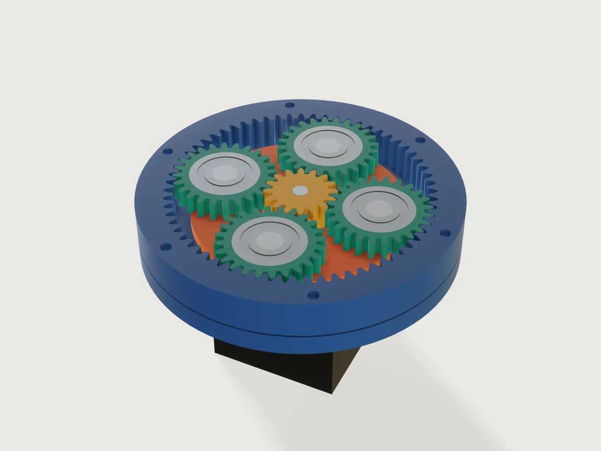
A printable single-stage planetary reducer for a NEMA stepper. Say which motor, how big the teeth may be, what reduction you want and how much room there is; the Jig picks the teeth so that the planets you ask for really assemble, gives every gear an involute tooth with the profile shift that keeps it free of undercut, keeps the ring's teeth clear of the planets, and carries the planets on ball bearings on steel pins between two carrier plates and the output on a pair of bearings in the cover. One slider turns the input, and sun, planets and carrier follow by the true kinematics: the flanks mesh at every angle, not only at zero.
What it shows
- A form that asks for the job, not the teeth. You give the motor, a tooth size, a reduction, a housing diameter and a
planet count;
sun_teeth,planet_teethandring_teethcome out of formulas. The tooth total is a whole multiple of the planet count (and even, so the planet teeth are whole), so (sun + ring) / planets is whole by construction: only what can be assembled can be entered. - Ranges that run one way (
variable.publishwith formula limits). Each range uses only the parameters above it in the form: the reduction's range follows from the module and the motor, the smallest housing from the reduction, the module and the motor (the sun must hold the motor shaft, the planet a bearing, the motor plate's spigot must clear the motor's screw heads), and the most planets from all of these (where neighbouring planets would come closer than 1 mm, worked out for 4, 5 and 6 planets with their own tooth counts). The reduction and housing limits are worked out for the worst tooth step of any planet count, so a planet count the form offers never makes them invalid. A sweep (an unpublished check: its script is not in this repository) of 168 272 combinations of the form (motor, module, reduction on its 0.1 grid, housing in 1 mm steps, every planet count offered, the extremes of backlash and clearance) found no empty range and no wall, fit or plate below its limit. - Involute gears drawn once, as arcs. Each gear is one tooth repeated by
sketch.patternwithchainandangleinto one closed profile and extruded once: each flank is three circular arcs through seven points of its involute, evenly spaced in roll angle, each arc's centre the circle through its three points worked out by formula; then a short radial foot, a root fillet arc and the tip and root arcs. The arcs leave the involute by at most 1.8 µm anywhere in the form's range (a calculation made for this Jig; the worst is a 14-tooth sun at module 2), far less than a printer holds, and the faces stay cylinders, which keeps the Jig light (Platform notes). Bores, pockets and bolt holes are circles in the same sketches. The Jig is created at a linear tolerance of 0.01 mm (file.new,meta.jsonnew). - Profile shift and ring-tip limits from the books. Sun, planet and ring are shifted together (
sun_shift, planet and ring the opposite, a V-0 pair that keeps the standard centre distance) so no gear is undercut; the ring's tips are shortened where the involute-interference limit needs it (ring_interference_limit). - A drive parameter, no assembly. Turn the input drives
feature.transformformulas: the sun by the input, the carrier by the input times sun over (sun + ring), each planet by the rolling it does on the sun. The slider runs to one full turn of the output. - Eight views from one choice (
feature.when, formula heights). Cutaway sections the reducer through the middle of the gears by making the gears' extrusions, the pins, the bearings and the motor shaft end there, so the involutes show without a single boolean; the parts above the cut are left out. Closed is the reducer as it is used. Print plates 1 to 6 each lay one group of printed parts flat in print orientation, inside a 220 × 220 mm bed, and nothing else: the model exports as a 3MF of that plate without picking. - Tables of bought parts (
table.set,choicesFrom): ISO 54 modules, NEMA motors, planet bearings chosen by formula from the room inside the planet, output bearings from the housing and the motor shaft.
A static model of a planetary set is one set of teeth at one angle. Here every reduction from 3.2 to 9.5, every planet count that fits and four modules give a real, meshing reducer that you can turn, and its print plates.
The real thing
How it works. The motor turns the sun (the input); the ring gear is held between the motor plate and the cover, each of which registers on its tooth tips with a spigot; the planets roll between sun and ring and carry the carrier round; the carrier, through the output hub and flange, is the output. With the ring held, one turn of the sun gives Zs / (Zs + Zr) of a turn of the carrier, the same way round: the reduction is 1 + Zr / Zs (KHK §17.1, Table 17.2, the planetary type, from Willis' relation).
Sources, what was read. The KHK Gear Technical Reference, printed edition (KHK Gears, gear_guide1.pdf), read for: Table 1.1 (efficiency of parallel-axis gears, 98.0 to 99.5 % per mesh, without bearing and lubricant losses), Table 3.1 and Fig. 3.1 (basic rack: addendum 1.00 m, dedendum 1.25 m, tooth depth 2.25 m, tip and root clearance 0.25 m, dedendum fillet radius 0.38 m), Table 3.2 (standard modules, extracted from JIS B 1701-2:1999, series I), eq. 3.4 and 3.5 (base pitch, contact ratio), eq. 3.7 to 3.10 (undercut and the profile shift that avoids it), Table 3.5 (tip land), Table 4.6 and eq. 4.4 to 4.9 (internal gears: tip and root, the shift convention, involute and trochoid interference), Table 6.1 and §6.3 (backlash), eq. 10.9 (contact ratio) and §17.1 (the three planetary conditions and the transmission ratio). The contact ratio of an internal pair and the involute-interference conditions were checked against eq. 3 to 6 of M. Savage, J. J. Coy and D. P. Townsend, Optimal Tooth Numbers for Compact Standard Spur Gear Sets, NASA TM-82614 (1981), NTRS; its scan is partly illegible, so it confirms the KHK forms rather than standing alone. ISO 53, ISO 21771 and Dudley's handbook were not read (paywalled or not to hand); KHK's rack and module tables are the JIS versions of ISO 53 and ISO 54. The NEMA 14, 17 and 23 bolt spacing (26, 31, 47.14 mm), pilot (22, 22, 38.1 mm, 2, 2, 1.6 mm deep) and shaft (5, 5, 6.35 mm) were read in the NEMA size table at hallikainen.org, which says of itself that its values "may or may not be right"; the screws are those most makers fit (M3, M3, M5). Shaft lengths vary with the maker: the 17HS4401 NEMA 17 is listed with a 5 mm shaft 21 mm long and a 40 N cm holding torque by Bits & Parts; other listings of the same type give 21 to 25 mm (search results, not read), so the Jig fits any shaft from 20 to 25 mm and tells you the longest. The bearing sizes (624, 625, 626, 608 of the 60 series; 61804, 61805, 61807) are from distributor listings and DIN 625-1 tabulations found by search, not a maker's datasheet: check the part you buy. The 220 × 220 mm bed is the build area Creality gives for the Ender-3, Ender-3 Pro, V2, Neo, V2 Neo, V3 SE and V3 (220 × 220 × 250 mm; 235 to 270 mm high for the V4, KE and S1) in its own Ender series parameter comparison, read 2026-11-09.
Tooth geometry.
module m, pressure angle α = 20°, addendum 1 m, dedendum 1.25 m        (KHK Table 3.1)
reference radius  r = m z / 2,  base radius rb = r cos α
tip radius        ra = r + m (1 + x)        root radius  rf = r − m (1.25 − x)
tooth half angle  ψ = (π/2 + 2 x tan α) / z − (backlash / 2) / (2 r)
Backlash is taken off the tooth thickness (KHK §6.3): each tooth is thinner by half the published backlash on its reference circle, so each mesh has that backlash in total and, centred, a normal gap of backlash · cos α / 2 on each flank. Below the involute each tooth has a short radial foot and a fillet of 0.3 m (0.25 m on the ring) tangent to the root circle: smaller than the rack's 0.38 m, so it stays below the mating tip's path. A real generated tooth has a trochoidal fillet instead; this one is simpler and printable. Each involute flank is drawn as three circular arcs, each through three of seven points of the involute taken at even steps of the roll angle t (x = rb (cos(φ + t) + t sin(φ + t)), y = rb (sin(φ + t) − t cos(φ + t))): by a calculation made for this Jig over all 1 312 tooth sets the form can make, they stay within 1.8 µm of the involute on the sun (a 14-tooth sun at module 2), 1.6 µm on a planet and 0.2 µm on the ring.
Undercut and shift. The limit is z = 2 / sin²α = 17.1 teeth (KHK eq. 3.7). A sun with fewer teeth takes the shift x_s = 1 − z_s sin²α / 2 + 0.02 (eq. 3.10 with 0.02 of margin), the planet and the ring take −x_s so the centre distance stays standard (KHK Table 4.6 for the ring's sign); a planet with fewer than 17 teeth makes the planet's own limit the one that counts. The form keeps sun + planet to at least 35 teeth, so both limits can be met at once.
Internal gear. Ring tip radius r_r − m (1 − x_r), root radius r_r + m (1.25 + x_r) (KHK Table 4.6). The ring keeps to
its involute: its tip is above its base circle (eq. 4.7), and its tip circle meets the line of action no nearer the ring's
base point than the planet's base point, rb_r² + (a sin α)² ≤ ra_r² (the involute-interference condition of eq. 4.4; NASA
eq. 5), so the Jig shortens the ring's tips where the standard addendum is too long (ring_interference_limit, by up to
0.28 mm in the form's range, at module 2, reduction 3.5, 138 mm). Trochoid interference (eq. 4.8 and 4.9) is computed and
asserted.
Assembly and kinematics. Coaxial condition Zr = Zs + 2 Zp (KHK eq. 17.1), assembly condition (Zs + Zr) / N whole (eq. 17.3), adjacency: the planets' tip circles clear each other (eq. 17.6). The Jig chooses the total T = Zs + Zr as the largest multiple of lcm(2, N) for which the ring still fits the housing, Zs = round(T / i), and the rest follows. Planet k sits at φk = (k − 1) 360° / N plus the carrier angle and is turned past φk by 180° − 180° / Zp − (θs − φk) Zs / Zp, θs the sun's angle; the ring is turned half a ring pitch when Zp is even. Planets 2 to 6 are five copies of planet 1, each placed by its own copy of that formula with k written in (a pattern cannot read its instance number: J-011); planet 1 is measured on both flanks against sun and ring, planets 2 to 6 together on both flanks against the ring. An independent program (an unpublished check: exact outlines as dense polygons, placed by these formulas, boundaries compared) found the normal flank gap equal to backlash · cos α / 2 within ±0.003 mm at 73 drive angles for 6 tooth sets and at 12 random angles for 14 random points of the form; on the model the gaps measure 0.0688 to 0.0698 mm in the Closed view at the defaults, against the 0.0705 mm designed.
Further limits, from the books' conditions, the numbers this Jig's own (the sweep above): at least 12 sun teeth and 2 mm of plastic round the motor's D bore at the sun's root; enough planet teeth for a 624 bearing and 1.6 mm of plastic round it; 1 mm between neighbouring planets; a tip land of at least 0.4 mm (a 0.4 mm nozzle), which limits the backlash on a small sun; contact ratios of at least 1.2 (1.54 and 2.02 at the defaults; KHK asks for 1 or more, NASA TM-82614 for more than 1.4 on standard gears); a housing of at most 160 mm, so that every plate fits a 220 mm bed.
Printing. PETG or ABS, 0.2 mm layers, four walls, 40 % infill or more on the gears. The six print plates, each in its own Show setting, each centred on a 220 × 220 mm bed with at least 5 mm free at every edge for a skirt or a brim (5.6 mm at the least, on plate 4 with the largest carriers; 15 mm or more on the others):
- Motor plate, on its floor (0.6 mm first-layer chamfer); the spigot and the screw recesses face up.
- Ring gear, upside down: its first layer lies at the cover joint, where nothing fits against its teeth, so the motor plate's spigot enters the clean end. Its teeth are vertical; no support. Both outer rims carry a 0.6 mm chamfer; the one at the cover joint is its first-layer chamfer.
- Cover, on its top face (0.6 mm chamfer): the bearing seat is vertical, and the lip that holds the output bearings is a 2.5 mm ring overhanging at the top of the print, which prints without support on most printers (support it if yours sags).
- Both carrier plates, bosses up (0.6 mm chamfer), side by side along the bed's diagonal, 6 mm apart.
- Output hub on its plate (0.6 mm chamfer), and the flange on its top face (0.8 mm chamfer; the screw recesses become a short bridge), side by side along the diagonal, 6 mm apart.
- Sun and planets, flat, the sun in the middle and the planets round it 6 mm clear of it and at least 9.5 mm from each other, the planets' bearing pockets up, with a 0.4 mm tip chamfer on the planets' bed side (a cone cut, built in the print plate only; see Platform notes). The sun needs none: its bottom 4.5 mm sit in the lower carrier's opening, below the planets, so its first layer never meshes.
Teeth print best from 1.25 mm modules up; at 1 mm they are small for a 0.4 mm nozzle (the tip lands stay above 0.4 mm but the flanks are only a few lines).
Assembly.
- Bolt the motor to the motor plate from inside (the screw heads sink into it); press the sun onto the D-shaft, slip fit 0.1 mm, with retaining compound, its bottom on the lower carrier's level (a 0.5 mm shim under it while it sets).
- Press a bearing into each planet from the top; the ledge underneath carries its outer ring and stays clear of the inner ring.
- Press the pins through the upper carrier plate into the hub's plate. Put the planets on the pins, set the lower carrier plate on the free ends (bosses towards the planets): the bosses of both plates hold the bearing inner rings.
- Set the ring gear on the motor plate (the spigot centres it). Lower the carrier with the hub into the ring, turning it until the planets mesh with ring and sun.
- Press the two output bearings into the cover from the top, down onto its lip, and lower the cover over the hub (its spigot centres it on the ring's tips; the hub's shoulder takes the lower inner ring). Bolt the flange onto the hub with three M3 screws into heat-set inserts (it clamps both inner rings), and the cover through the ring gear into M3 heat-set inserts in the motor plate, with screws in the length window the form gives (48.5 to 50 mm at the defaults: an M3 × 50). Grease the teeth.
A load pressing the output down (a turntable) goes from the inner rings through the balls into the outer rings and the cover's lip; a pull upward is held only by the bearings' press fit in the cover.
Bought parts. One ball bearing per planet and a dowel pin per planet (sizes are outputs: 608, 8 × 22 × 7 mm, and 8 mm pins of 26 mm at the defaults); two 618-series output bearings (61804 20 × 32 × 7, 61805 25 × 37 × 7 or 61807 35 × 47 × 7 mm); M3 screws and inserts; the motor's own screws.
What this Jig does not claim. No strength or life: tooth root stress, contact stress and wear of printed gears are not calculated, and the strength of PLA or PETG teeth is not proven; what a printed gear carries is a matter for a test on your own print. The form gives the output torque per N m of motor torque at most: the reduction times 0.98² (two meshes at the low end of KHK Table 1.1, which leaves out bearing and lubricant losses and assumes accurately made gears); with the 17HS4401's 40 N cm holding torque that is at most 1.9 N m at the defaults, and a printed set will lose more. Nor are the D-shaft joint, the press fits of the pins or the bearings' load in printed seats calculated. Press fits are modelled at nominal size and usually need reaming or a test print; printed plastic on steel creeps. The backlash is what you set, plus your printer's error.
Parameters
| Group | Parameter | Range | What it changes |
|---|---|---|---|
| The reducer | Motor | NEMA 14, 17, 23 | Mounting screws, pilot, shaft, the sun's bore and the smallest housing |
| The reducer | Tooth size (module) | 1, 1.25, 1.5, 2 mm | Tooth size, strength and printability; a bigger module needs a bigger housing |
| The reducer | Reduction | from 3.2 to 9.5 at module 1 (8.9 on a NEMA 23), 9.2 at 1.25, 7.7 at 1.5, 5.8 at 2 | The tooth counts; the output Reduction you get shows the true ratio, within 6 % |
| The reducer | Housing outer diameter | a minimum from the reduction, module and motor (98 mm at the defaults) to 160 mm (142 mm at module 1, where the ring has its most teeth, 125) | How many teeth fit, every radial size, the output bearings |
| The reducer | Planets | 3 to the most that keep 1 mm between them (4 at the defaults) | How many planets; the tooth total follows so they assemble |
| Motion | Turn the input | 0 to one turn of the output | Runs the reducer: sun, planets, carrier and output turn by the true kinematics |
| Gears | Gear width | from the planet bearing's width + 3 mm to 30 mm | Face width of the teeth and the height of the stack |
| Gears | Backlash | 0.1 mm to 0.4 mm, less where a small sun's tip land would fall under 0.4 mm (0.14 mm at the least) | Thins every tooth so each mesh has that total play |
| Gears | Print clearance | 0.05 to 0.5 mm | Running and register fits: the spigots in the ring's tips, the sun in the lower carrier, the planet's ledge round the boss |
| View | Show | Cutaway, Closed, Print plate 1 to 6 | See What it shows |
Outputs: the teeth (sun, planet, ring, and counted on the model), the reduction you get and the one computed from the counted teeth, the output's turn at this input, both contact ratios, the sun's profile shift, the gap between planets, the planet bearing and pin size and the pin length, the output bearings, the shortest and longest cover screw, the output torque per N m of motor torque at most, the longest motor shaft that fits, and the reducer's height above the motor face.
Checks
The Jig carries 72 assertions; each is active in the views where the parts it measures exist. In words:
- Counts and ratio, on the model (Cutaway and Closed). As many planet bodies as asked; sun, planet and ring teeth counted as flank faces of the bodies equal the numbers drawn; ring = sun + 2 planets (counted); (sun + ring) / planets whole (counted: the assembly condition); the reduction from the counted teeth equals the one the form shows, and that is within 6 % of the one asked for.
- Tooth outlines, closed form. The volumes of sun, planet and ring gear against the closed form of the outline (the involute's area, foot, fillet, tip and root arcs, less the bore, pocket, holes and the ring's rim chamfers), within 0.3 %, wherever the gear is shown; the formula was compared with the polygon areas of the independent program to five digits.
- Tooth thickness and tip circles, measured. The area of each gear's tip faces (exact cylinders) against the tip land of KHK Table 3.5 with this Jig's backlash, written apart from the sketches' own variables, times the face width, within 0.3 %: a tooth drawn too thick or too thin, a backlash left out, or a ring tip on the wrong circle fails it.
- The meshes, measured (Closed view). For planet 1, the least distance (
measure.distance) from its leading flanks (all three arcs of every tooth) to the sun's flanks that face them, and from its trailing flanks likewise, and the same against the ring; for planets 2 to the last together, from their leading flanks and from their trailing flanks to the whole ring gear: each between 0.6 and 1.45 times the design gap backlash · cos α / 2. A planet turned off its phase narrows one of its gaps below the bound, which the least gap of planets 2 to the last then shows; a planet run into the ring's teeth gives 0 (measured to the whole ring, so that the other planets' good gaps cannot hide it). The lower bound is proven: the measure refines its proof until the bound clears 0.6 times the gap and stops there, so the bound it reports sits just above that. Planet 1 is measured to the sun's facing flanks because to the whole sun, with its end faces, the proof could not be refined to the bound at three points of the range (0.024 mm proven of 0.097 mm found). - Kinematics and centre distance, measured (Cutaway and Closed). Planet 1's centre of mass is where the carrier must be at this input, at the centre distance m (Zs + Zp) / 2 computed from the counted teeth (x and y, within 0.02 mm); in the Closed view an index mark on the flange is checked the same way. The common centre of mass of all the planets lies on the axis (x and y, within 0.01 mm), so a planet copy off its place by a quarter of a millimetre (towards the sun, say) is caught; the planet copies are each placed by their own copy of the formula.
- Gear conditions. Contact ratios at least 1.2; no undercut on sun or planet; the ring's tip above its base circle and outside the involute-interference limit; trochoid interference at or above zero; tip lands of at least 0.4 mm; neighbouring planets at least 1 mm apart (measured, Closed view).
- Registers and running fits, measured (Closed view). The motor plate's spigot and the cover's spigot each stand
between 0.5 and 1.5 times the print clearance from the ring's tooth tips, and a section through each measures twice
the ring's tip radius less the print clearance across (
sectionExtent), so the spigot is inside the tips, not in the teeth; the planet pins stand on the planets' axes (the gap to planet 1's ledge is the same all round); the planet's ledge runs clear of the carrier boss and at least 0.1 mm (0.3 mm designed) off the bearing's inner ring; the cover's lip stays at least 0.15 mm off the output bearing's inner ring; the sun's tips clear the lower carrier's opening by 0.9 times the print clearance or more; the output hub clears the ring gear. - Walls. Every wall of motor plate, lower carrier, cover, output hub and flange at least 1.2 mm (
measure.thickness), measured on the part's own print plate (a wall does not depend on the view); ring wall at least 7 mm, planet wall round its bearing at least 1.2 mm, sun wall round the shaft at least 1.5 mm (by formula); a 20 mm motor shaft reaches 8 mm into the sun and a 25 mm one still fits; the housing is the diameter asked (measured). - Nothing overlaps when closed (Closed view): the carrier plates, hub, cover, motor plate, output bearings, planet
bearings and planet pins, in pairs (
overlap). The gears are left out of this set: they are covered by the mesh distances. - Print plates. Every printed part lies on the bed; the plate's parts stay at least 5 mm (
bed_margin) inside every edge of the 220 × 220 mm bed, room for a skirt or a brim (fourboxMin/boxMaxassertions; a sweep of the layout formulas over 84 136 combinations of motor, module, reduction, housing, planets and clearance found 5.6 mm the least); no two parts on a plate overlap.
Mutation tests, on scratch copies of the build, 18 of them, each failing at least one assertion cleanly (status failed, not only an error or notProven; Closed view, 35° input): planet 3 turned half a tooth (both mesh checks of planets 2 to the last); a planet pin moved 0.4 mm (the pins-on-axes check; the overlap check cannot be measured there); the carrier's pin holes 0.5 mm small (the overlap check); the motor plate's spigot 0.3 mm into the ring's teeth and the cover's likewise (their register checks and section diameters); the planet's ledge pushed into the boss (both ledge checks); the cover's lip pushed onto the inner ring (the lip check); planet 1 turned by +0.6 and by −0.6 of its backlash angle and planet 2 by half a tooth (mesh checks); the centre distance 0.05 mm short (planet 1's centre of mass); tooth totals that do not divide by three planets (the counted assembly condition and the mesh of planets 2 to the last); a wrong carrier angle (the meshes and both turn checks); the ring's half-pitch phase left out (every ring mesh); a planet drawn without its share of backlash (its tip-land area; its meshes narrow to half the gap, within the document's 0.01 mm tolerance of the bound, so they are notProven); the ring tip left unshortened where the limit binds (module 2, reduction 3.5, 138 mm: the ring's tip-land area and the interference condition); the sun's teeth 0.004 rad thinner (the sun's tip-land area); planet 4 moved 0.25 mm towards the sun (the planets' common centre of mass, x). Planet 4 moved 0.06 mm stays inside every bound (its gaps change by 0.02 mm).
By hand (param.set), what the form refuses at the defaults (NEMA 17, module 1.25, reduction 5, 100 mm, 4 planets): a
housing of 90 mm (98 mm is the least for this reduction) and one of 170 mm (160 mm is the most), five planets (four is the
most that keep 1 mm between them), and a reduction of 6 in this housing (it would need at least 109 mm). Points tried by
hand, each passing every assertion active in its view: NEMA 23 at module 1.25, reduction 5, 114 mm, four planets; NEMA 17
at module 1, reduction 3.2, 99 mm; NEMA 23 at module 1, reduction 3.2, 110 mm; NEMA 23 at module 2, reduction 5.8, 160 mm, three planets;
module 1.5 at reduction 3.2 in 160 mm with four planets, 30 mm gears and 0.5 mm clearance, closed and on each of the six
print plates; module 1 at reduction 3.2 in 125 mm with six planets, closed and on plate 6.
tools/jigs.py check runs check-range (defaults, the corners of the ranges, every choice, 32 random points from seed 1):
the result is in meta.json stats. Beyond it, the Closed view was run at 220 points with the backlash at its least
(0.1 to 0.11 mm, where the mesh bounds have the least room): every mesh assertion proven at every point. Not checked: the
strength of anything (above), the printed fits, and planets 2 to the last against the sun: they are placed by copies of
planet 1's formula, whose sun mesh is measured; their ring meshes and their common centre are measured.
Export
- To print: set Show to Print plate 1, then File › Export, The model, as 3MF: the plate's parts in print orientation, within 220 × 220 mm, with no bought part and no helper body. Do the same for plates 2 to 6. Plate 6 holds the sun and every planet.
- Assembly for CAD: set Show to Closed and export STEP.
The README in the model's repository has the rest (Files, Rebuild, Difficulty, Platform notes, Licence): the whole README on GitHub.