
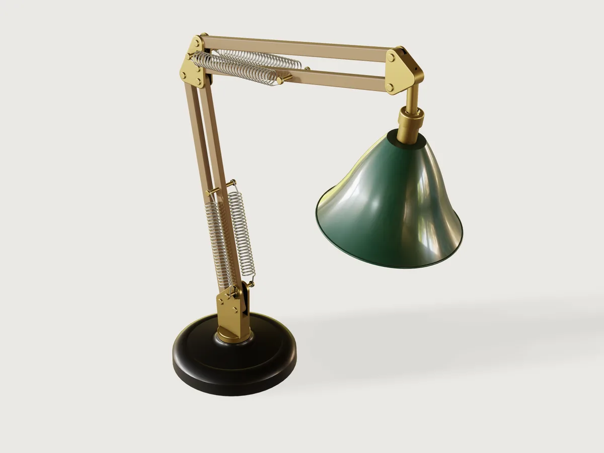
An original two-arm desk lamp balanced by four extension springs: oak parallelogram arms, brass elbow and head plates, a heavy cast-iron base, and a spun steel shade in deep green enamel that swivels on a free ball joint. It follows the classic spring-balanced lamp type (not any maker's design) and proves the point of that type: the torque about each arm's pivots, computed from the model's own masses and solved joint angles and from real springs, stays within a stated pivot friction over the whole sweep of poses.
What it shows
- Two parallelogram loops. Each arm is a closed four-bar of
mate.addrevolutes (turret, two oak bars, elbow knuckle, and knuckle, two oak bars, head block), so the elbow and the head stay level whatever the arms do. Both loops are solved in oneassembly.solve. - Springs that are configurations following
t. A spring part'sspanis passed byparamsas a formula oft(lower_span,upper_span); each moment of the motion is a new configuration of the coil. The coil is the cheapest form that is honest about its wire and coil count (below). - The spring as a joint. A spring is a two-force member of variable length: a
revoluteat its anchor stud, aslideralong its axis to a separate end hook, and arevolutewhere that hook hangs on the arm's cross-pin. The loop closes throughassembly.solve; theslider'sjointDistanceis the difference between the coil's drawn length and the solved anchor span, and is asserted to be zero. - A ball mate left free. The shade hangs on
Shade_swivel(mate.add, kindball), and turns by hand. - A means of preload, and fixings a fitter can follow. Friction pivots with leather washers set the arms' holding moment; the turret is held by a screw, the ball by a screwed cap, the lamp holder by its nipple in the cup.
- Mass from materials, balance from the solved model.
material.preset,body.materialfor the brass and leather;variable.measureofmass,centerOfMass,jointAngle,jointDistance,position, androtationover the instances;variable.outputfor the torques;assert.addovermotion.check. - Limits and pose.
limitson the arm mates (2° outside the sweep) and on the turret; the base turn is a public pose parameter. - Fits bounded from both sides. Each fit's lower side is a
clearanceassertion with amin(its proven lower bound); its upper side is the sameclearanceas an output (variable.measure, the gap found between a real pair of points) under avalueassertion with amax. Side play is measured per bar against its two plates and per plate against its bars, so one loose bar or one wide slot shows. A loosened fit fails as a tight one does. - Shared sizes are assembly variables. The pin diameter, the cheek and oak bores, the cross-pin bore, the bar's width
and thickness and the slot and cheek half-widths are each one variable of the assembly, passed to every part that uses
them by
params. - One part, many configurations.
arm-bar(four bars, three configurations by length and pin position),pivot-pin(eight instances, three configurations),friction-pivot(two, two configurations),spring-stud(four, two configurations),spring(four, two spans per moment) andspring-tip(four).
The real thing
Reference for the principle. M J French and M B Widden, The spring-and-lever balancing mechanism, George Carwardine and the Anglepoise lamp, Proc IMechE Part C 214 (2000), pp. 501-508, read in full (Lancaster eprints 20295):
- A mass
mat radiusron an arm is balanced in every pose by a spring from a point a heightcstraight above the arm's pivot to a point atbon the arm, if the spring has zero free length and stiffnessk = mgr / bc(its Eq. 1; arrangement of its Fig. 2b). WithF = k (a - l0)andl0not zero, exact balance is impossible (its Eq. 8 to 10). - With two arms on parallelograms, the spring on each arm balances that arm alone (its Section 3.1 and Fig. 3a). The lower spring carries the whole upper assembly as a weight at the elbow; the upper spring only the head.
- A spring wound with pre-tension has an effective free length shorter than its close-wound length; the paper says it is possible to reach zero or even a negative value (its Section 2.3). Their appendix notes that Carwardine knew friction keeps the arm in place in spite of small errors such as deviations from linearity.
This model applies Section 3.1 with the masses of the bodies it actually draws, and adds what the paper leaves out for a real wound spring: its stated free length.
The spring is a stated calculation, not a catalogue item. Formulae and data read:
k = G d⁴ / (8 D³ N)and the Wahl factor are as given on Firgelli Automations' spring-rate calculator page and RoyMech's Springs helical;Ti = π τi d³ / (8 D)andKw = (4C − 1)/(4C − 4) + 0.615/Cfrom RoyMech.- Initial stress: RoyMech's table of best initial tension stress against spring index. At C = 11 the range is 55 to 90 N/mm²; this model uses 83 N/mm², inside it.
- Music wire ASTM A228, modulus in torsion 79.3 GPa, design stress 45 % of minimum tensile strength (Master Spring & Wire Form Co., Properties of materials, read). The minimum tensile strength of 0.063 in (1.6 mm) wire is 293,000 psi, 2020 MPa, from Gibbs Wire & Steel's data sheet No. 1004, Phosphate coated music wire, "Tensile Strength Table (ASTM-A228 spec)" (read; the standard itself was not). The allowable shear stress is then 45 % of 2020 MPa, 909 MPa.
- Coiled length with initial tension
Lz = 1.03 (n + 1) dand the geometric limit4 ≤ D/d ≤ 16are from the Autodesk Inventor extension-spring help page.
| Spring (one design, four instances) | ||
|---|---|---|
| Wire, mean coil, index | 1.6 mm, 17.6 mm, C = 11 | music wire ASTM A228 |
| Active coils | 26 | |
Rate k |
0.458 N/mm | formula above, G = 79.3 GPa |
Initial tension Ti |
7.6 N | 83 N/mm² initial stress |
Free length eye to eye L0 |
72.7 mm | 1.03 (N + 1) d + 2 × 0.8 D end hooks |
Effective free length e = L0 - Ti / k |
56.1 mm | not zero |
| Largest force at the allowable stress | 73.5 N | 909 MPa, Wahl-corrected (Kw = 1.131); that force is reached at a span of 216.4 mm |
| Largest force in the sweep | 55.5 N | at a span of 177.3 mm (upper springs) |
Why the springs are not zero-free-length. Zero effective free length needs Ti / k = L0: 33.3 N of initial
tension, an initial stress of about 364 MPa with the end hooks counted (223 MPa counting the coiled body, 1.03 (N + 1) d, alone), far
outside the 55 to 90 MPa RoyMech gives as the best range for this index. French and Widden describe winding springs to
zero free length as possible; no source was found for how far beyond the published range a winder can go, so this model
stays within it and is honest about e. The balance is then not exact: with φ the arm's lean from vertical, the net
torque is sin φ · (m g r − n F b c / s), which does not vanish in every pose. The anchor height c is chosen so the
residual stays small over the sweep, and the check is that it stays within a stated pivot friction.
The reach along each arm is fixed (lower_reach 180 mm, upper_reach 170 mm), and the anchor heights are formulas
(lower_anchor_height 28.7 mm and upper_anchor_height 20.3 mm at the defaults) of the arm length and of an estimated
load (named estimates such as head_fittings_mass, checked against the measured masses), so that the balance follows the
public parameters. The upper reach is 170 mm so that, at the largest shade and the longest arms, the upper anchor stays
low enough (24.7 mm, worked out) for the stud to clear the knuckle's aux pivot pin above it; an assertion measures that
clearance. The checks use the measured masses, not the estimate.
| At the stored pose (from the model's outputs) | Lower arm | Upper arm |
|---|---|---|
| Measured load carried | 0.898 kg at the elbow | 0.617 kg at the head |
| Lean from vertical | −10° | 78° |
| Solved spring span | 151.8 mm | 167.0 mm |
| Force per spring | 43.9 N | 50.8 N |
| Gravity torque | −0.533 N m | 2.107 N m |
| Spring torque (two springs) | −0.518 N m | 2.055 N m |
| Net torque | −0.015 N m | 0.052 N m |
Over the whole sweep (73 samples) the largest net torque is 0.023 N m on the lower arm and 0.089 N m on the upper arm, against a friction of 0.293 N m per arm at the stated clamp (below).
Parts and process.
- Base: sand-cast iron, a turned-looking revolve with cast draft (the outer wall is 2.2°), filleted edges from the profile's own arcs, a bore for the turret's stem and a counterbored hole from underneath for the screw that holds it; black enamel.
- Turret: a turned brass foot and stem and two cheeks from 4 mm brass plate, joined; the stem is tapped M5 at its end
for a steel shoulder screw (
turret-screw) that comes up through the base, keeps the turret in when the lamp is lifted by its arm, and sets 0.1 mm of end float. - Arm bars: oak slats 15 × 9 mm, grain along the length, rounded along their edges and at the ends, with brass pins in
plain oak bores. They are drawn in a plain oak colour with no grain texture (
material.presetoak,"pattern": null; see Platform notes). A pressed bronze bush would be used on a production lamp and is left out: it is hidden, and it does not change anything this model proves. - Knuckle and head plates: 3 mm brass cheeks cut from sheet with a spacer, deburred and edge-rounded; a turned brass hollow stem on the head, Ø 12 with a Ø 7 bore for the flex, threaded M12 × 1 at its end (thread not drawn) for the ball.
- Shade: metal-spun 0.7 mm steel sheet, enamelled deep green outside and cream inside (the cream is drawn as a
separate 0.25 mm layer of the same sheet, see Platform notes), with a rolled rim. A turned brass cup, fixed through the
shade's top, holds the ball: its seat is open above the equator so the ball goes in from the top, and a brass cap
(
ball-cap, M22 × 1, thread not drawn) screwed over it closes the seat above the ball (mouth Ø 16.3 against the Ø 18 ball). The ball (ball) is a separate turned piece, tapped M12 × 1 right through, screwed onto the stem after the cap has been passed over the stem (the cap's mouth is too small to pass the ball), and locked on its thread with a thread-locking compound, so the shade's swivel torque cannot unscrew it. The drawn ball joint is free. The shade and lamp's centre of mass lies about 100 mm below the ball, so a real joint needs about 0.1 N m of friction to hold a tilt: a compressible liner in the seat, not drawn, tightened by the cap. Nothing stops the shade turning about its own axis on the ball, so the flex can be twisted without limit. A real lamp needs a stop, for example a pin in the cup running in a groove cut along a meridian of the ball, which leaves both tilts free. It is not drawn, because the ball mate cannot be limited (A-004) and a drawn groove would prove nothing here. The maker must add it and verify it. - Lamp: an E27 holder sleeve and an A60-size bulb (E27 is the 27 mm Edison thread, read from Wikipedia's Edison screw; an A60 lamp is 60 mm wide, read from Wikipedia's A-series light bulb). Its hollow M10 nipple (Ø 7 bore, thread not drawn) screws into the cup's bore, so the holder's shoulder clamps the shade's top against the cup. The cap and the insulator inside the sleeve are not drawn; the bulb is drawn solid at a density that gives it the mass of a hollow bulb.
- Flex: H03VV-F 2 × 0.5 mm², the light two-core PVC flex for desk lamps. Read: Caledonian's data sheet gives 5 mm approximate overall diameter, a static bending radius of 4 × Ø and a flexing radius of 7.5 × Ø; RR Kabel gives 5.1 mm and the same radii; Nexans gives 5.9 mm as the largest diameter. A 90° turn into the holder inside the cup would need about 20 mm of radius (4 × 5.1), more than a Ø 22 cup holds, so the flex runs on the shade's axis instead. It enters the top of the head's nose, runs down the stem's Ø 7 bore, through the ball's Ø 12.2 bore and the cup's Ø 10.2 bore, and down the nipple's Ø 7 bore to the holder: every bore takes the largest 5.9 mm flex. It bends only where the shade is tilted, between the stem's end at the ball's centre and the nipple's top 16 mm below; both bore mouths are radiused (1.5 mm at the stem's end, 1 mm at the nipple's top), which also takes the sharp metal edge off a mains flex. The tilt stop is measured: posing the shade in scratch copies, the cap's crown clears the stem by 1.28 mm at the stored 10°, 0.37 mm at 18°, 0.014 mm at 20.0° and overlaps it at 20.5°, so the shade tilts at most about 20° from the stem (the ball mate itself cannot be limited or posed by an assertion, A-004). The bend at the stop is worked out, not measured: an arc of radius R that leaves the stem's axis and joins the shade's axis touches them R tan(10°) from the stem's end, 6.7 mm for R = 38 mm (7.5 × 5.1, the flexing radius) and 7.8 mm for R = 44 mm (7.5 × 5.9). So the flex is straight again before the nipple's top, 16 mm away. At the stem's end the arc lies 0.6 to 0.7 mm off the stem's axis, inside the radiused mouth (bore radius 5 mm there). Where the radius ends, 1.5 mm up, it lies 0.45 mm off, against the 0.55 mm a Ø 5.9 flex has in the Ø 7 bore. So the flex can bend at its flexing radius at the stop. Outside, the flex leaves the nose in a loose loop and runs along the arms in clips to the base. The flex and its clips are not drawn.
- Springs: close-wound and stretched in service from the 73 mm free length. Each end is an open hook: a half ring of wire with a 5.6 mm gap and a straight leg to the coil, so it goes onto a Ø 5 shank between the heads of a stud or cross-pin.
Fits. Brass pivot pins Ø 5.0 (pin_diameter) in cheek bores Ø 5.2 (cheek_bore, 0.1 mm radial) and oak bores Ø 5.3
(oak_bore, 0.15 mm radial); bars 9.0 mm (bar_thickness) in a 9.8 mm slot (cheek_inner 4.9 mm, 0.4 mm a side); turret stem Ø 16.0 in the base bore Ø 16.4; turret seat 0.1 mm above the boss; ball
Ø 18 in a seat Ø 18.3. These are stated running fits, not fit classes, and each is bounded from above as well as below
(Checks). The studs screw into an M5 tapped hole in the cheek (drawn at the Ø 5.2 of the other holes; the stud's thread drawn at
Ø 4.8, clear of it, F-014) until their collar bears on its
outer face. The spring cross-pins are pressed: Ø 5.0 in a Ø 4.9 oak bore, 0.05 mm radial interference, listed as a contact.
A clearance between two bodies is their smallest gap, so each fit is drawn with its own gap the smallest of its pair:
the pin heads stand 0.3 mm off the cheeks (more than the cheek bores' 0.2 mm upper bound), and each stud's thread
stands 0.2 mm clear in its hole (more than the collar's 0.1 mm upper bound). A loose bore or an unseated collar then
shows instead of hiding behind another gap.
Pivot friction, and where it comes from. Bars float 0.4 mm a side in their slots, so most pivots have only journal
friction. The two pivots that hold the arms have a means of preload: friction-pivot, at the main pivot of each arm
(Lower_main at the turret, Upper_main at the knuckle). It is an M5 tension screw through both cheeks with a clamp nut
and a conical spring washer, and a 0.5 mm leather washer each side of the bar, in the 0.4 mm space between bar and cheek.
The leather is drawn at its free thickness, so it overlaps the bar and the cheek by 0.05 mm each side (listed as
contacts): squeezed, it fills the space, and the screw's tension passes through cheek, leather, bar, leather, cheek
without bending the cheeks. That matters at the turret, whose 4 mm cheeks are too stiff to be pulled together through
a gap. The screw head and the spring washer are drawn 0.3 mm off the cheeks.
The holding moment is 2 μ F r_m: two faces, μ = 0.3 (the low end of leather on wood, 0.3 to 0.4, Engineering
Toolbox's Friction and friction coefficients, clean and dry), and the mean radius for uniform wear, the more cautious
of the two usual assumptions, r_m = (Ro + Ri) / 2 = 4.88 mm for a washer of radii 2.75 and 7 mm (uniform pressure
would give 5.18 mm). Both formulas are written from engineering practice, not from a source read here. The design sets
the clamp at F = 100 N, so arm_friction = 0.293 N m per arm; nothing in the model measures the clamp.
What the fitter must set. The arms stay where they are left provided the clamp is at least 31 N (the largest net torque of the drawn springs and lamp, 0.089 N m), and at least 80 N to cover a spring rate of ±10 % (the largest net torque of the tolerance runs below, 0.233 N m). A fitter checks it with the springs unhooked and the arm upright: the bar must need at least 0.23 N m to start turning on its friction pivot, a pull of 0.71 N (about 72 g) square to the arm at 330 mm from the pivot. Journal friction at the other six pivots is ignored, which is conservative.
The spring is drawn honestly and cheaply. The coil has its real wire and real coil count, at the pitch its stretched
length gives. Each turn is two half-turn tori (feature.revolve of the wire section through 180°), near and far, tilted
either way by the half-turn's own lead, and joined end to end; feature.pattern repeats the two banks along the axis. Each
joint is tangent, the height of the wire between joints differs from a true helix by a fraction of the pitch, and the
far end of the spring meets a separate end hook (spring-tip) that the slider joint carries. In a side-by-side render
against a true helical sweep of the same wire and coil count it read the same. Each end hook is a half ring and a
straight leg, not a formed hook. The span the coil is drawn at is rounded to 0.25 mm (span_quantum): the moments of
the motion then share configurations (cheaper bake), and the sliding joint carries the difference to the solved span,
asserted to stay within half that step. See Platform notes.
Safety. The model proves a balance within a stated friction, and that the springs stay within the stress limit above. It proves nothing about the wiring, the lamp's heat, or mains safety. Whoever makes and sells a real lamp approves it against the luminaire safety standard that applies where it is sold.
Parts and assembly order
| Part | Count | What |
|---|---|---|
base |
1 | Cast-iron base, revolved, with a bore for the turret's stem and a screw hole from below |
turret |
1 | Brass foot and stem, two cheeks carrying the two lower pivots and the spring studs |
turret-screw |
1 | Steel shoulder screw that keeps the turret in the base |
arm-bar |
4 | Oak slats of two arms |
knuckle |
1 | Brass elbow plate with four pivots and the upper spring studs |
head-block |
1 | Brass head block with a stem for the ball |
ball |
1 | Turned brass ball, screwed onto the stem |
shade |
1 | Spun steel bell, outer shell and cream liner, with a brass ball cup (three bodies) |
ball-cap |
1 | Brass cap screwed over the cup, keeps the ball in |
lamp |
1 | E27 holder and A60 bulb (two bodies) |
friction-pivot |
2 | M5 tension screw, nut, spring washer, two 0.5 mm leather washers (five bodies), at the main pivot of each arm |
pivot-pin |
8 | Brass pins in three configurations by length: 6 pivots, 2 spring cross-pins |
spring-stud |
4 | Brass M5 studs with a collar, on the cheeks' outer faces |
spring |
4 | Coil and rear end hook, per arm two spring configurations per moment |
spring-tip |
4 | The far end hook of each spring |
To build one, in order:
- Pass the turret's stem into the base bore and screw the shoulder screw up into it from under the base.
- Press the spring cross-pins into the two main bars and rivet over their second heads.
- Set the bars into the turret's and knuckle's slots. At the six plain pivots pass a pin through the cheeks and bar and
rivet its second head. At the two friction pivots (
Lower_main,Upper_main) slip a leather washer either side of the bar, pass the tension screw, fit the spring washer and clamp nut, and tighten until the pivot needs the torque given above to turn (springs not yet hooked). - Close the upper arm on the head block the same way (pins riveted).
- Screw the four studs into the cheeks until their collars seat.
- Hook the springs on the studs and cross-pins: their open hooks go on between the heads, stretching each spring by hand with the arm held.
- Screw the lamp holder's nipple up through the shade's top into the cup's bore, so its shoulder clamps the shade against the cup.
- Pass the ball cap over the head's stem and screw the ball onto the stem with thread-locking compound. Thread the flex down through the nose, the stem and the ball, then through the cup and the nipple, and wire the holder. Drop the ball into the cup's open seat, screw the cap down over the cup, and fit the bulb.
The motion
t plays a closed sweep of poses. Each arm's lean from vertical follows a cosine (lower_angle, upper_angle),
lower_angle swinging from −28° (back) to +46° (forward) and upper_angle from 44° (up) to 108° (down past level), out
of phase, so the head traces a closed path over the desk and the shade stays level through the two parallelograms.
t = 0 is the stored pose, with the shade tilted 10° on its ball by its placement. The cycle closes on itself
(meta.json motion).
What is free. assembly.solve reports 3 degrees of freedom, all three on Shade_swivel: the shade turns on its
ball by hand in all three directions. The base's turn (Turret_swivel) is the public parameter Base turn, driven by
that parameter and held at it over the motion; limits of ±170° model a stop on the swivel (a stored value, not a
collision check). The ball mate holds no orientation: its turns stay where the placement sets them.
Parameters
| Parameter | Range | Default | What it does |
|---|---|---|---|
| Arm length | 290 to 350 mm, step 10 | 330 mm | Length between pivots of both arms; the springs' anchor heights follow, their reach along the arm stays at 180 and 170 mm |
| Base diameter | 180 to 220 mm, step 5 | 180 mm | Diameter of the base; below 180 mm, with the longest arms and the largest shade, the lamp's centre of mass would be within 10 mm of the rim |
| Shade diameter | 150 to 190 mm, step 5 | 170 mm | Diameter of the shade; the anchors follow its mass |
| Base turn | −170° to 170°, step 5° | 0° | Pose of the lamp on its swivel |
Checks
At the stored pose (document.check, and at t = 0 at each corner of the ranges): the assertions below, and these
fits, bounded from both sides:
- the pins in each bar's oak bores 0.1 to 0.25 mm (0.15 nominal), the pins in each plate's cheek bores 0.05 to 0.2 mm
(0.1 nominal), the bars in each slot 0.2 to 0.6 mm a side (0.4 nominal). The lower side is a
clearanceassertion per bar or plate; the upper side is onevalueassertion on the largest of the outputs: per bar for the oak bores, per plate for the cheek bores, and for side play both per bar (each bar against its two plates) and per plate; - Leather washers fill the slot at the lower/upper friction pivot: the leather's thickness, measured as the two
washers'
volumeover twice their area, less the measured side play in that slot (the plate'sclearanceoutput), is 0.04 to 0.2 mm, a squeeze of 0.02 to 0.1 mm a side (0.05 nominal). A loose or a crushed leather fails it (mutations below); - the spring cross-pins pressed into their bars (
overlap, is); - the studs' collars seated on their cheeks within 0.02 to 0.1 mm (the lower side per plate, the upper side per stud);
- each fixing, with the same split: the lamp nipple in the cup's bore (0.05 to 0.2 mm), the holder shoulder under the shade's top (0.02 to 0.1 mm), the ball in the cap's and the cup's seats (0.05 to 0.3 mm), and the turret's shoulder screw held to 0.05 to 0.15 mm of the base;
- the upper studs clear the knuckle's aux pivot pin by at least 0.3 mm (5.2 mm at the defaults; a minimum only);
- Load estimates match the measured masses: the design estimate of the load on the lower arm within 6 % of the measure.
Over the motion (motion.check, 73 samples, at the defaults and at 8 of the 16 corners of the ranges):
- Lower arm balances within its pivot friction and Upper arm balances within its pivot friction: the net torque is
within
arm_friction(0.293 N m, from the friction pivot above). Gravity comes from themassof the measured groups and the measuredjointAngle; the spring from the real force at the solved span, with the anchor height itself worked out from the solved span and angle, so a stud in the wrong place shows. Largest value at the defaults: 0.023 and 0.089 N m. - Springs stay within their stroke, lower/upper: each span between the free length plus 50 mm (a margin chosen for this model, with no source behind it) and the span at the allowable force (216.4 mm); the sweep uses 151.3 to 161.4 mm below and 156.0 to 177.3 mm above.
- Drawn lower/upper springs reach their pins: the drawn coil's length, rounded to 0.25 mm, is within half that step of the solved span at every sample (largest 0.124 mm).
- Elbow follows the lower arm: the knuckle's measured height against the closed form
pivot_z + L cos(lean). - Head stays level: the x and y components of the head's rotation (its turn about z is the base turn) within 0.05°.
- Shade rim clears the desk: the lowest point of the shade stays at least 20 mm above the desk (71 mm at the defaults).
The arm
limitssit 2° outside the sweep. With both arms at those limits at once, the largest shade and the shortest arms, the rim is 9.70 mm above the desk, measured on the model (boxMinof the shade, a scratch run with the two drives set to the limits; 29.29 mm with the longest arms). No sample of the motion puts both arms at their limits, so this is a measurement, not an assertion. - Lamp does not tip: the measured centre of mass of the whole lamp stays at least 10 mm inside the base's rim (at most 62.5 mm from the axis at the defaults, against a base radius of 90 mm).
- No collision between bodies at the 121 moments the tool checks at the defaults and the 31 it checks at each of 8 of the 16
corners of the ranges, other than the listed contacts in
meta.json: each spring's two end hooks, where the wire of the hook runs into the coil (one wire, drawn as separate bodies); the cross-pins pressed into the oak; the shade's shell and its cream liner (one sheet, drawn as two bodies).
Mutation tests, in a scratch copy, each at 73 samples (largest net torque over the sweep, lower and upper arm):
| Mutation | Net torque (N m) | What failed |
|---|---|---|
| Turret's spring stud drilled 5 mm higher, in the part only | 0.375, 0.089 | Lower arm balances and Drawn lower springs reach their pins (4.8 mm) |
| Upper anchor height 3 mm too large | 0.023, 0.320 | Upper arm balances |
| Shade in 1.4 mm sheet instead of 0.7 mm, anchors not redesigned | 0.535, 0.800 | both balances, Load estimates, the holder's clamp on the shade |
| Wire 1.5 mm instead of 1.6 mm, anchors frozen at the design's values | 0.411, 0.459 | both balances |
Oak bores 5.8 mm (oak_bore, 0.4 mm radial) |
0.023, 0.089 | Every bar's pins have their running fit in the oak (0.40 mm against 0.25) |
| Turret slot 1 mm wider, in the turret only | 0.023, 0.089 | Every bar has its side play in every slot (0.90 mm against 0.6) and Leather washers fill the slot at the lower friction pivot (−0.40 mm) |
| Only the upper aux bar 8.4 mm thick, inside its published range (the reviewer's) | 0.020, 0.086 | Every bar has its side play in every slot (0.70 mm against 0.6) |
| Only the upper right stud's collar 0.3 mm off its cheek, inside its range (the reviewer's) | 0.023, 0.089 | Every stud seats on its cheek (0.20 mm against 0.1; the stud's 0.2 mm thread gap caps the gap found) |
Cheek bores 5.6 mm (cheek_bore, 0.3 mm radial) |
0.022, 0.088 | Every plate's pins have their fit in the cheek bores (0.30 mm against 0.2) |
| Leather 0.25 mm instead of 0.5 mm: loose | 0.023, 0.089 | both Leather washers fill the slot (−0.15 mm) |
| Leather 0.75 mm: crushed | 0.023, 0.089 | both Leather washers fill the slot (0.35 mm) |
Tolerance and load margin. These runs (scratch copy, 73 samples, anchors left as designed) show how much the friction covers beyond the drawn springs and lamp:
| Change | Net torque, lower and upper | Result |
|---|---|---|
| Spring rate 10 % below nominal | 0.173, 0.233 N m | holds |
| Spring rate 10 % above nominal | 0.201, 0.186 N m | holds; its force at the longest stretch, 60.5 N, stays under the allowable 73.5 N |
| 50 g more at the head (a heavier bulb, or a cord's share hanging from the head) | 0.109, 0.225 N m | holds |
So, with the clamp set as above, a spring made to a rate tolerance of ±10 % and up to 50 g more at the head still leave each arm where it is put. A cord is not modelled: one clipped along the arms and hanging from the head must stay within that 50 g, or the anchors be reset for it. Beyond that the arms would need adjustable anchors, which this design does not have.
What the samples do not cover. Nothing between the samples is claimed; the sweep is one cosine in each arm. The spring forces are the static formula, without hysteresis, fatigue or hook-end stress. The lamp's balance is asserted at the base's turn of the stored pose and at the corners of the range.
The README in the model's repository has the rest (Files, Rebuild, Difficulty, Platform notes, Licence): the whole README on GitHub.